|
数据搜索系统,热门电子元器件搜索 |
|
|
数据搜索系统,热门电子元器件搜索 |
|
AS3953 数据表(PDF) 11 Page - ams AG |
|
|
|||||||||||||||||||||||||||||
AS3953 数据表(HTML) 11 Page - ams AG |
|
|
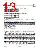
11 / 42 page  www.ams.com Revision 1.0 11 - 42 AS3953 Datasheet - D e t a il e d D es c r i pt io n 7.3 Power Manager Power manager is controlling the positive supply voltage of the PICC Logic, EEPROM and SPI Interface (VDD). Its inputs are VP_INT (rectified and regulated supply extracted from PCD field) and the VP_SPI (SPI power supply from external). In standby mode, when the AS3953 is not in a PCD field (condition is that rectified supply voltage is below HF_PON threshold) and the SPI is not active (/SS is high) the VDD supply is disconnected not to consume on VP_SPI. The only consumption on VP_SPI is leakage of level shifters and SPI pins. When the AS3953 is placed in a PCD field the VDD is connected to VP_INT. This happens once the VP_INT level is above the HF_PON threshold. VP_SPI is connected to VDD only when the AS3953 is not in the PCD field (rectified supply voltage is below HF_PON threshold) and the SPI interface is activated by pulling /SS signal low. The switch to VP_SPI is controlled by /SS signal. The deactivation is delayed by 0.7ms min., thus the switch stays on in case the time between successive SPI activations shorter. During EEPROM writing, which is activated over the SPI, the switch is also active. At activation of the switch the time between the falling edge of /SS signal and rising edge of SCLK has to be at least 50µs to allow charging of internal VDD buffer capacitor and expiration of POR signal. Please note that the only SPI operations, which are allowed in this mode, are reading and writing of the EEPROM and registers. Figure 5. Power Manager Concept 7.4 ISO 14443A Framing Mode When Framing mode is selected the PICC logic performs receive and transmit framing according to the selected ISO 14443A bit rate. During reception it recognizes the SOF, EOF and data bits, performs parity and CRC check, organizes the received data in bytes and places them in the FIFO. During transmit, it operates inversely, it takes bytes from FIFO, generates parity and CRC bits, adds SOF and EOF and performs data encoding. Default bit rate in the Framing mode is fc/128 (~106 kb/s). Higher data rates may be configured by controller by writing the Bit Rate Definition Register. In order to respect the PCD-to-PICC frame delay according to ISO14443-3 at data rate fc/128 bit the PICC logic synchronizes the response to the beginning of the next response window, but not earlier than window with n=9. In this mode the EEPROM can be accessed via SPI when the RF field is active. DELAY VP_INT VP_SPI VDD PON /SS EEPROM WRITE |
|
链接网址 |
| ALLDATASHEET是否为您带来帮助? [ DONATE ] |
关于 Alldatasheet | 广告服务 | 联系我们 | 隐私政策 | 数据表链接 | 链接交换 | 制造商名单 All Rights Reserved©Alldatasheet.com |
| Russian : Alldatasheetru.com | Korean : Alldatasheet.co.kr | Spanish : Alldatasheet.es | French : Alldatasheet.fr | Italian : Alldatasheetit.com Portuguese : Alldatasheetpt.com | Polish : Alldatasheet.pl | Vietnamese : Alldatasheet.vn Indian : Alldatasheet.in | Mexican : Alldatasheet.com.mx | British : Alldatasheet.co.uk | New Zealand : Alldatasheet.co.nz |
|
Family Site : ic2ic.com |
icmetro.com |
 Chinese ▼
 English
 Chinese
 German
 Japanese
 Russian
 Korean
 Spanish
 French
 Italian
 Portuguese
 Polish
 Vietnamese
 Indian
 Mexican
 British
 New Zealand