|
数据搜索系统,热门电子元器件搜索 |
|
|
数据搜索系统,热门电子元器件搜索 |
|
P9222-R 数据表(PDF) 36 Page - Renesas Technology Corp |
|
|
|||||||||||||||||||||||||||||
P9222-R 数据表(HTML) 36 Page - Renesas Technology Corp |
|
|
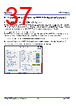
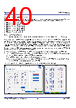
36 / 58 page  P9222-R/RN Datasheet © 2019-2022 Renesas Electronics Corporation 36 May 5, 2022 8.8 Configuration of P9222-R/RN Parameters The P9222-R/RN firmware provides great flexibility to customize operating parameters for custom applications. Default values of the P9222- R/RN operating parameters such as output voltage, FOD parameters, and current limit are set in the firmware programmed into the internal one-time programmable (OTP) memory. Based on the end application, the P9222-R/RN operating parameters can be configured by either writing to internal SRAM registers via the I2C interface, or by loading the user configuration generated by the P9222-R/RN GUI into an external EEPROM. The register map in “Registers” describes all the SRAM registers that can be configured via the I2C interface. The SRAM registers content is volatile and all the content resets to default after every power cycle. The AP must update the operating parameters after every power cycle. The AP can use the VRECTON interrupt or battery charger interrupt as a trigger to update the SRAM registers. If the end application does not have an external AP to update operating parameters, a generic purpose external EEPROM with I2C interface can be connected to the P9222-R/RN I2C port, and the GP2 pin needs to be tied to LDO1P8 using a 10K resistor. Using the P9222-R/RN Windows GUI, the operating parameters can be customized and a custom configuration file for the external EEPROM can be generated. The configuration file can be loaded into the external EEPROM using the I2C interface and the P9222-R/RN Windows GUI. Write protect on EEPROM needs to be disabled before writing the configuration to the external EEPROM. If the GP2 pin is tied to LDO1P8, the P9222-R/RN accesses the external EEPROM during startup before turning on the main output LDO, and then sets the default operating parameters to the values set in the external EEPROM configuration. 8.9 P9222-R/RN Internal Register Access by Application Processor The user registers are located in the SRAM space starting from address 0x0000, and are accessible via the standard I2C interface. The P9222- R/RN I2C device address is 0x61. Some of the registers are 2 bytes long (16-bit). The P9222-R/RN microprocessor updates the memory location by writing both bytes in a single clock. The I2C bus reads the bytes sequentially, and it is possible to split the read value between old and new value. If a critical decision must made based on a value, the register of interest needs to be read two or more times until the same number appears in two consecutive read operations. The Internal register map is listed in “Registers”. 8.10 External EEPROM Access by P9222-R/RN An external EEPROM with an I2C interface can be connected to the P9222-R/RN I2C pins, and the user configuration generated from the P9222-R/RN Windows GUI can be loaded into the external EEPROM to configure the default values of the P9222-R/RN operating parameters (e.g., FOD parameters). The P9222-R/RN polls the GP2 state during startup. If the GP2 pin is high, the P9222-R/RN will become an I2C master and quickly read 100 bytes of the user configuration data from the external EEPROM. After reading the data, the P9222-R/RN will revert back to its default I2C slave state and then check the data integrity of the read data using a checksum calculation. If the data checksum matches correctly, the P9222-R/RN overrides the default values of the operating parameters set in the OTP firmware with the new values from the external EEPROM. If the data checksum does not match, the P9222-R/RN continues to use the default values of the operating parameters set in the OTP firmware. Register 0xD2 can be polled to check whether the P9222-R/RN is using the configuration from an external EEPROM or the default OTP configuration. The external EEPROM I2C device address is 0x50. The 24AA128T external EEPROM is used in the P9222-R/RN reference design. A0, A1, and A2 pins are tied to GND in the design. Write-protect must be disabled while the user configuration in the external EEPROM is updated. An external EEPROM to configure the operating parameters is typically used when there is no I2C master in the application accessing the P9222-R/RN. If there is another I2C master on the same I2C bus that the P9222-R/RN and external EEPROM is also using, it is recommended to add an I2C switch to avoid potential I2C bus contention. |
|
链接网址 |
| ALLDATASHEET是否为您带来帮助? [ DONATE ] |
关于 Alldatasheet | 广告服务 | 联系我们 | 隐私政策 | 数据表链接 | 链接交换 | 制造商名单 All Rights Reserved©Alldatasheet.com |
| Russian : Alldatasheetru.com | Korean : Alldatasheet.co.kr | Spanish : Alldatasheet.es | French : Alldatasheet.fr | Italian : Alldatasheetit.com Portuguese : Alldatasheetpt.com | Polish : Alldatasheet.pl | Vietnamese : Alldatasheet.vn Indian : Alldatasheet.in | Mexican : Alldatasheet.com.mx | British : Alldatasheet.co.uk | New Zealand : Alldatasheet.co.nz |
|
Family Site : ic2ic.com |
icmetro.com |
 Chinese ▼
 English
 Chinese
 German
 Japanese
 Russian
 Korean
 Spanish
 French
 Italian
 Portuguese
 Polish
 Vietnamese
 Indian
 Mexican
 British
 New Zealand