|
数据搜索系统,热门电子元器件搜索 |
|
|
数据搜索系统,热门电子元器件搜索 |
|
P9222-R 数据表(PDF) 40 Page - Renesas Technology Corp |
|
|
|||||||||||||||||||||||||||||
P9222-R 数据表(HTML) 40 Page - Renesas Technology Corp |
|
|
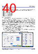
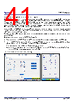
40 / 58 page  P9222-R/RN Datasheet © 2019-2022 Renesas Electronics Corporation 40 May 5, 2022 9.4.1 Configuring FOD Parameters FOD parameters consist of 8 sections. Each section is divided by output current and consists of gain and offset to compensate for Rx internal power loss; each section is also adjusted for Reported Rx power. The following comprises the mA ranges for the FOD sections: FOD section [0] is from 0mA to 191mA FOD section [1] is from 192mA to 351mA FOD section [2] is from 352mA to 511mA FOD section [3] is from 512mA to 671mA FOD section [4] is from 672mA to 819mA FOD section [5] is more than 820mA The formula of Rx Reported Power is: ������������������������������������������������������������������������������������������������������������������������������������������������������������������������������������[0..5]=������������������������������������������������������������(������������������������������������������������������������������������������������������������������������������������������������������������������������������������������������������������)∗������������������������������������������������������������������������������������[0…5]+������������������������������������������������������������������������[0..5] Equation6 Place the receiver with the P9222-R/RN on the Nok9 FOD transmitter. Ramp the current on the output of the P9222-R/RN in steps of 50mA to 100mA and monitor power difference between the Nok9 transmitted power and the receiver reported power value. The difference should be within 0-350mW. If the difference exceeds 350mW, adjust the FOD gain or FOD offset of that particular output current section in order to bring the difference back to 0-350mW range. The AP can modify the FOD gain and FOD offset by writing to the Foreign Object Detection Registers (0x70-0x7E). In the final product, the AP can use the VRECTON interrupt or battery charger interrupt as a trigger to update the FOD registers. The default values of the FOD registers can also be configured by the following writing a configuration file into the external EEPROM. To generate the configuration file using the P9222-R/RN Windows GUI: 1. Place the receiver with the P9222-R/RN onto the WPC transmitter or apply 5V from an external power supply on the VRECT node. 2. Launch the P9222-R/RN GUI, go to the “Config” tab, click the “Rd EEPROM” button, and then click the “FOD” button. A new popup window with the current FOD values stored in the external EEPROM will be displayed. 3. Enter new FOD values and click on the “Save cfg file” to generate a new configuration. The configuration can also be directly written into the external EEPROM by clicking the “Wr EEPROM” button. Note: The Write Protect function on the EEPROM must be disabled before writing to the EEPROM. Figure 34. Changing the Default FOD Registers using the P9222-R/RN Windows GUI |
|
链接网址 |
| ALLDATASHEET是否为您带来帮助? [ DONATE ] |
关于 Alldatasheet | 广告服务 | 联系我们 | 隐私政策 | 数据表链接 | 链接交换 | 制造商名单 All Rights Reserved©Alldatasheet.com |
| Russian : Alldatasheetru.com | Korean : Alldatasheet.co.kr | Spanish : Alldatasheet.es | French : Alldatasheet.fr | Italian : Alldatasheetit.com Portuguese : Alldatasheetpt.com | Polish : Alldatasheet.pl | Vietnamese : Alldatasheet.vn Indian : Alldatasheet.in | Mexican : Alldatasheet.com.mx | British : Alldatasheet.co.uk | New Zealand : Alldatasheet.co.nz |
|
Family Site : ic2ic.com |
icmetro.com |
 Chinese ▼
 English
 Chinese
 German
 Japanese
 Russian
 Korean
 Spanish
 French
 Italian
 Portuguese
 Polish
 Vietnamese
 Indian
 Mexican
 British
 New Zealand