|
数据搜索系统,热门电子元器件搜索 |
|
|
数据搜索系统,热门电子元器件搜索 |
|
P9222-R 数据表(PDF) 41 Page - Renesas Technology Corp |
|
|
|||||||||||||||||||||||||||||
P9222-R 数据表(HTML) 41 Page - Renesas Technology Corp |
|
|
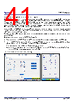
41 / 58 page  P9222-R/RN Datasheet © 2019-2022 Renesas Electronics Corporation 41 May 5, 2022 9.4.2 Modulation Capacitor and Interrupt Enables The P9222-R/RN sends the communication packets to the transmitter using ASK modulation of the coil voltage. For ASK modulation, the P9222-R/RN switches on and off the capacitors on the COM1, COM2, CMA, and CMB pins using internal MOSFETs. By default, the P9222- R/RN switches only MOSFETs on the COM1 and COM2 pins. ASK modulation depth can be increased by enabling the switches on the CMA and CMB pins. Measure the modulation depth on the transmitter demodulation circuitry, and if too small, adjust the ASK modulation depth by enabling the CMA and CMB switches. Modulation depth can also be increased by increasing the capacitor value. The AP can also change the ASK modulation depth by writing to the ASK modulation depth Registers (0xF4). Using the /INT pin, the P9222-R/RN can interrupt the AP when there is a fault condition such as overcurrent or when there is a major state change such as when the VRECT is turned on. The AP can enable or disable the interrupt conditions by writing to the Interrupt Enable Registers, INT_Enable_L (0x38) and INT_Enable_H (0x39). The default values of the ASK modulation depth and the interrupt enable registers can also be configured by writing a configuration file into the external EEPROM. To generate the configuration file using the P9222-R/RN Windows GUI: 1. Place the receiver with the P9222-R/RN onto the WPC transmitter or apply 5V from an external power supply on the VRECT node. 2. Launch the P9222-R/RN GUI, go to the “Config” tab, click the “Rd EEPROM” button, and then click the “MODcap,INT,ID” button. A new popup window with the current values stored in the external EEPROM will be displayed. 3. Enter new values and click on the “Save cfg file” to generate a new configuration. The configuration can also be directly written to the external EEPROM by clicking the “Wr EEPROM” button. Note: The Write Protect function on the EEPROM must be disabled before writing to the EEPROM. Figure 35. Modulation and INT Settings Tab |
|
链接网址 |
| ALLDATASHEET是否为您带来帮助? [ DONATE ] |
关于 Alldatasheet | 广告服务 | 联系我们 | 隐私政策 | 数据表链接 | 链接交换 | 制造商名单 All Rights Reserved©Alldatasheet.com |
| Russian : Alldatasheetru.com | Korean : Alldatasheet.co.kr | Spanish : Alldatasheet.es | French : Alldatasheet.fr | Italian : Alldatasheetit.com Portuguese : Alldatasheetpt.com | Polish : Alldatasheet.pl | Vietnamese : Alldatasheet.vn Indian : Alldatasheet.in | Mexican : Alldatasheet.com.mx | British : Alldatasheet.co.uk | New Zealand : Alldatasheet.co.nz |
|
Family Site : ic2ic.com |
icmetro.com |
 Chinese ▼
 English
 Chinese
 German
 Japanese
 Russian
 Korean
 Spanish
 French
 Italian
 Portuguese
 Polish
 Vietnamese
 Indian
 Mexican
 British
 New Zealand