|
数据搜索系统,热门电子元器件搜索 |
|
|
数据搜索系统,热门电子元器件搜索 |
|
RC19302A00AGNT#KD0 数据表(PDF) 35 Page - Renesas Technology Corp |
|
|
|||||||||||||||||||||||||||||
RC19302A00AGNT#KD0 数据表(HTML) 35 Page - Renesas Technology Corp |
|
|
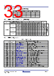
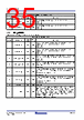
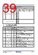
35 / 62 page  R31DS0210EU0106 Rev.1.06 Page 35 May 11, 2026 RC193xx Datasheet 4.5.3 LOS_CONFIG Loss of Signal and Async Mode Configuration Register. 1 rb_oeb_1 RO 0x0 State of OEb1 pin. The default pin state is 1 if not driven to a 0. 0 = Pin low 1 = Pin high 0 rb_oeb_0 RO 0x0 State of OEb0 pin. The default pin state is 1 if not driven to a 0. 0 = Pin low 1 = Pin high LOS_CONFIG Bit Field Descriptions Bit Field Field Name Field Type Default Value Description 7 los1b_rw1c_en RW 0x1 LOS sticky bit enable for CLKIN1. Enables the CLKIN1 LOS sticky bit (B0x27[1]). This bit must be set to 1 if B0x4[2] is set to 0. 0 = Disable 1 = Enable 6 los0b_rw1c_en RW 0x1 LOS sticky bit enable for CLKIN0. Enables the CLKIN0 LOS sticky bit (B0x27[1]). This bit must be set to 1 if B0x4[2] is set to 0. 0 = Disable 1 = Enable 5 los1b_acp1_enable RW 0x1 Automatic clock parking enable for bank 1. Enables Automatic Clock Parking of bank 1 (CLK[7:4]) outputs to a low/low state when LOS condition occurs. 0 = Disable 1 = Enable 4 los0b_acp0_enable RW 0x1 Automatic clock parking enable for bank 0. Enables Automatic Clock Parking of bank 0 (CLK[3:0]) outputs to a low/low state when LOS condition occurs. 0 = Disable 1 = Enable 3 los1b_config RW 0x1 Configure LOSb pin operating mode for CLKIN1. Determines if the LOSb pin is real-time or sticky. If sticky, the LOSb pin is driven by the LOS1b RW1C sticky bit. 0 = LOSb from bank 1 RW1C sticky bit 1 = LOSb real-time 2 los0b_config RW 0x1 Configure LOSb pin operating mode for CLKIN0. Determines if the LOSb pin is real-time or sticky. If sticky, the LOSb pin is driven by the LOS0b RW1C sticky bit. 0 = LOSb from bank 0 RW1C sticky bit 1 = LOSb real-time 1 reserved RW 0x0 Reserved 0 async_mode RW 0x0 Enable asynchronous operating mode. SYNC mode is the normal mode of operation, where the input clock is continuous. Outputs stop and start in a glitch free manner. ASYNC mode is used when the input is a pulse instead of a clock. All glitch-free synchronization circuits are bypassed, minimizing the latency through the device. ASYNC mode cannot be used with LOS or ACP. B0x4[6] and B0x4[4] must be set to 0 if ASYNC mode is used. 0 = SYNC mode, glitch-free outputs 1 = ASYNC mode, non-glitch-free outputs OEB_PIN_READBACK Bit Field Descriptions Bit Field Field Name Field Type Default Value Description |
|
链接网址 |
| ALLDATASHEET是否为您带来帮助? [ DONATE ] |
关于 Alldatasheet | 广告服务 | 联系我们 | 隐私政策 | 数据表链接 | 链接交换 | 制造商名单 All Rights Reserved©Alldatasheet.com |
| Russian : Alldatasheetru.com | Korean : Alldatasheet.co.kr | Spanish : Alldatasheet.es | French : Alldatasheet.fr | Italian : Alldatasheetit.com Portuguese : Alldatasheetpt.com | Polish : Alldatasheet.pl | Vietnamese : Alldatasheet.vn Indian : Alldatasheet.in | Mexican : Alldatasheet.com.mx | British : Alldatasheet.co.uk | New Zealand : Alldatasheet.co.nz |
|
Family Site : ic2ic.com |
icmetro.com |
 Chinese ▼
 English
 Chinese
 German
 Japanese
 Russian
 Korean
 Spanish
 French
 Italian
 Portuguese
 Polish
 Vietnamese
 Indian
 Mexican
 British
 New Zealand