|
数据搜索系统,热门电子元器件搜索 |
|
|
数据搜索系统,热门电子元器件搜索 |
|
EM357-RTR 数据表(PDF) 37 Page - List of Unclassifed Manufacturers |
|
|
|||||||||||||||||||||||||||||
EM357-RTR 数据表(HTML) 37 Page - List of Unclassifed Manufacturers |
|
|
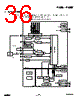
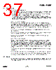
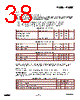
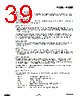
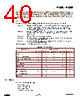
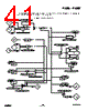
37 / 240 page  EM351 / EM357 6.1 Power domains The EM35x contains three power domains: An “always-on domain” containing all logic and analog cells required to manage the EM35x’s power modes, including the GPIO controller and sleep timer. This domain must remain powered. A “core domain” containing the CPU, Nested Vectored Interrupt Controller (NVIC), and peripherals. To save power, this domain can be powered down using a mode called deep sleep. A “memory domain” containing the RAM and flash memories. This domain is managed by the power management controller. When in deep sleep, the RAM portion of this domain is powered from the always- on domain supply to retain the RAM contents while the regulators are disabled. During deep sleep the flash portion is completely powered down. 6.1.1 Internally regulated power The preferred and recommended power configuration is to use the internal regulated power supplies to provide power to the core and memory domains. The internal regulators (VREG_1V25 and VREG_1V8) generate nominal 1.25 V and 1.8 V supplies. The 1.25 V supply is internally routed to the core domain and to an external pin. The 1.8 V supply is routed to an external pin where it can be externally routed back into the chip to supply the memory domain. The internal regulators are described in Chapter 16, Integrated Voltage Regulator. When using the internal regulators, the always-on domain must be powered between 2.1 V and 3.6 V at all four VDD_PADS pins. When using the internal regulators, the VREG_1V8 regulator output pin (VREG_OUT) must be connected to the VDD_MEM, VDD_PADSA, VDD_VCO, VDD_RF, VDD_IF, VDD_PRE, and VDD_SYNTH pins. When using the internal regulators, the VREG_1V25 regulator output and supply requires a connection between both VDD_CORE pins. 6.1.2 Externally regulated power Optionally, the on-chip regulators may be left unused, and the core and memory domains may instead be powered from external supplies. For simplicity, the voltage for the core domain can be raised to nominal 1.8 V, requiring only one external regulator, or the core domain can be powered from the on-chip regulators while the other domains are powered externally. Note that if the core domain is powered at a higher voltage (1.8 V instead of 1.25 V) then power consumption increases. A regulator enable signal, REG_EN, is provided for control of external regulators. This is an open-drain signal that requires an external pull-up resistor. If REG_EN is not required to control external regulators it can be disabled (see section 7.3, Forced Functions in Chapter 7, GPIO). Using an external regulator requires the always-on domain to be powered between 1.8 V and 3.6 V at all four VDD_PADS pins. When using an external regulator, the VREG_1V8 regulator output pin (VREG_OUT) must be left unconnected. When using an external regulator, this external nominal 1.8 V supply has to be connected to both VDD_CORE pins and to the VDD_MEM, VDD_PADSA, VDD_VCO, VDD_RF, VDD_IF, VDD_PRE and VDD_SYNTH pins. 6.2 Resets The EM35x resets are generated from a number of sources. Each of these reset sources feeds into central reset detection logic that causes various parts of the system to be reset depending on the state of the system and the nature of the reset event. 6-2 120-035X-000D Preliminary |
|
链接网址 |
| ALLDATASHEET是否为您带来帮助? [ DONATE ] |
关于 Alldatasheet | 广告服务 | 联系我们 | 隐私政策 | 数据表链接 | 链接交换 | 制造商名单 All Rights Reserved©Alldatasheet.com |
| Russian : Alldatasheetru.com | Korean : Alldatasheet.co.kr | Spanish : Alldatasheet.es | French : Alldatasheet.fr | Italian : Alldatasheetit.com Portuguese : Alldatasheetpt.com | Polish : Alldatasheet.pl | Vietnamese : Alldatasheet.vn Indian : Alldatasheet.in | Mexican : Alldatasheet.com.mx | British : Alldatasheet.co.uk | New Zealand : Alldatasheet.co.nz |
|
Family Site : ic2ic.com |
icmetro.com |
 Chinese ▼
 English
 Chinese
 German
 Japanese
 Russian
 Korean
 Spanish
 French
 Italian
 Portuguese
 Polish
 Vietnamese
 Indian
 Mexican
 British
 New Zealand