|
数据搜索系统,热门电子元器件搜索 |
|
|
数据搜索系统,热门电子元器件搜索 |
|
EM357-RTR 数据表(PDF) 44 Page - List of Unclassifed Manufacturers |
|
|
|||||||||||||||||||||||||||||
EM357-RTR 数据表(HTML) 44 Page - List of Unclassifed Manufacturers |
|
|
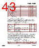
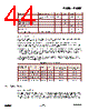
44 / 240 page  EM351 / EM357 6-9 120-035X-000D Preliminary Parameter Test conditions Min Typ Max Unit Accuracy Initial, temperature, and ageing -100 +100 ppm Load capacitance OSC32A 27 pF Load capacitance OSC32B 18 pF Crystal ESR 100 kΩ Start-up time 2 s Current consumption At 25°C, VDD_PADS=3.0 V 0.5 μA 6.3.5 Clock Switching The EM35x has two switching mechanisms for the main system clock, providing four clock modes. Table 6-10 shows these clock modes and how they affect the internal clocks. The register bit OSC24M_CTRL_OSC24M_SEL in the OSC24M_CTRL register switches between the high- frequency RC oscillator (OSCHF) and the high-frequency crystal oscillator (OSC24M) as the main system clock (SYSCLK). The peripheral clock (PCLK) is always half the frequency of SYSCLK. The register bit CPU_CLKSEL_FIELD in the CPU_CLKSEL register switches between PCLK and SYSCLK to produce the ARM ® CortexTM-M3 CPU clock (FCLK). The default and preferred mode of operation is to run the CPU at the higher PCLK frequency, 24 MHz, to give higher processing performance for all applications and improved duty cycling for applications using sleep modes. In addition to these modes, further automatic control is invoked by hardware when flash programming is enabled. To ensure accuracy of the flash controller’s timers, the FCLK frequency is forced to 12 MHz during flash programming and erase operations. Table 6-10. System Clock Modes FCLK OSC24M_CTRL_ OSC24M_SEL CPU_CLKSEL_FI ELD SYSCLK PCLK Flash Program/Erase Inactive Flash Program/Erase Active 0 (OSCHF) 0 (Normal CPU) 12 MHz 6 MHz 6 MHz 12 MHz 0 (OSCHF) 1 (Fast CPU) 12 MHz 6 MHz 12 MHz 12 MHz 1 (OSC24M) 0 (Normal CPU) 24 MHz 12 MHz 12 MHz 12 MHz 1 (OSC24M) 1 (Fast CPU) 24 MHz 12 MHz 24 MHz 12 MHz 6.4 System Timers 6.4.1 Watchdog Timer The EM35x integrates a watchdog timer which can be enabled to provide protection against software crashes and ARM ® CortexTM-M3 CPU lockup. By default, it is disabled at power up of the always-on power domain. The watchdog timer uses the calibrated 1 kHz clock (CLK1K) as its reference and provides a nominal 2.048 s timeout. A low water mark interrupt occurs at 1.792 s and triggers an NMI to the ARM ® CortexTM-M3 NVIC as an |
|
链接网址 |
| ALLDATASHEET是否为您带来帮助? [ DONATE ] |
关于 Alldatasheet | 广告服务 | 联系我们 | 隐私政策 | 数据表链接 | 链接交换 | 制造商名单 All Rights Reserved©Alldatasheet.com |
| Russian : Alldatasheetru.com | Korean : Alldatasheet.co.kr | Spanish : Alldatasheet.es | French : Alldatasheet.fr | Italian : Alldatasheetit.com Portuguese : Alldatasheetpt.com | Polish : Alldatasheet.pl | Vietnamese : Alldatasheet.vn Indian : Alldatasheet.in | Mexican : Alldatasheet.com.mx | British : Alldatasheet.co.uk | New Zealand : Alldatasheet.co.nz |
|
Family Site : ic2ic.com |
icmetro.com |
 Chinese ▼
 English
 Chinese
 German
 Japanese
 Russian
 Korean
 Spanish
 French
 Italian
 Portuguese
 Polish
 Vietnamese
 Indian
 Mexican
 British
 New Zealand