|
数据搜索系统,热门电子元器件搜索 |
|
|
数据搜索系统,热门电子元器件搜索 |
|
EM357-RTR 数据表(PDF) 51 Page - List of Unclassifed Manufacturers |
|
|
|||||||||||||||||||||||||||||
EM357-RTR 数据表(HTML) 51 Page - List of Unclassifed Manufacturers |
|
|
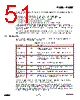
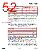
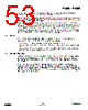
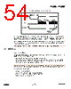
51 / 240 page  EM351 / EM357 Each of the three GPIO ports has the following registers whose low-order eight bits correspond to the port’s eight GPIO pins: GPIO_PxIN (input data register) returns the pin level (unless in analog mode). GPIO_PxOUT (output data register) controls the output level in normal output mode. GPIO_PxCLR (clear output data register) clears bits in GPIO_PxOUT. GPIO_PxSET (set output data register) sets bits in GPIO_PxOUT. GPIO_PxWAKE (wake monitor register) specifies the pins that can wake the EM35x. In addition to these registers, each port has a pair of configuration registers, GPIO_PxCFGH and GPIO_PxCFGL. These registers specify the basic operating mode for the port’s pins. GPIO_PxCFGL configures the pins Px[3:0] and GPIO_PxCFGH configures the pins Px[7:4]. For brevity, the notation GPIO_PxCFGH/L refers to the pair of configuration registers. Five GPIO pins (PA6, PA7, PB6, PB7 and PC0) can sink and source higher current than standard GPIO outputs. Refer to Table 2-5, Digital I/O Specifications in Chapter 2, Electrical Characteristics, for more information. 7.2 Configuration Each pin has a 4-bit configuration value in the GPIO_PxCFGH/L register. The various GPIO modes and their 4-bit configuration values are shown in Table 7-1. Table 7-1. GPIO Configuration Modes GPIO Mode GPIO_PxCFGH/L Description Analog 0x0 Analog input or output. When in analog mode, the digital input (GPIO_PxIN) always reads 1. Input (floating) 0x4 Digital input without an internal pull up or pull down. Output is disabled. Input (pull-up or pull-down) 0x8 Digital input with an internal pull up or pull down. A set bit in GPIO_PxOUT selects pull up and a cleared bit selects pull down. Output is disabled. Output (push- pull) 0x1 Push-pull output. GPIO_PxOUT controls the output. Output (open- drain) 0x5 Open-drain output. GPIO_PxOUT controls the output. If a pull up is required, it must be external. Alternate Output (push-pull) 0x9 Push-pull output. An onboard peripheral controls the output. Alternate Output (open-drain) 0xD Open-drain output. An onboard peripheral controls the output. If a pull up is required, it must be external. If a GPIO has two peripherals that can be the source of alternate output mode data, then other registers in addition to GPIO_PxCFGH/L determine which peripheral controls the output. Several GPIOs share an alternate output with Timer 2 and the Serial Controllers. Bits in Timer 2’s TIM2_OR register control routing Timer 2 outputs to different GPIOs. Bits in Timer 2’s TIM2_CCER register enable Timer 2 outputs. When Timer 2 outputs are enabled they override Serial Controller outputs. Table 7-2 indicates the GPIO mapping for Timer 2 outputs depending on the bits in the register TIM2_OR. Refer to Chapter 9, General Purpose Timers for complete information on timer configuration. 7-2 120-035X-000D Preliminary |
|
链接网址 |
| ALLDATASHEET是否为您带来帮助? [ DONATE ] |
关于 Alldatasheet | 广告服务 | 联系我们 | 隐私政策 | 数据表链接 | 链接交换 | 制造商名单 All Rights Reserved©Alldatasheet.com |
| Russian : Alldatasheetru.com | Korean : Alldatasheet.co.kr | Spanish : Alldatasheet.es | French : Alldatasheet.fr | Italian : Alldatasheetit.com Portuguese : Alldatasheetpt.com | Polish : Alldatasheet.pl | Vietnamese : Alldatasheet.vn Indian : Alldatasheet.in | Mexican : Alldatasheet.com.mx | British : Alldatasheet.co.uk | New Zealand : Alldatasheet.co.nz |
|
Family Site : ic2ic.com |
icmetro.com |
 Chinese ▼
 English
 Chinese
 German
 Japanese
 Russian
 Korean
 Spanish
 French
 Italian
 Portuguese
 Polish
 Vietnamese
 Indian
 Mexican
 British
 New Zealand