|
数据搜索系统,热门电子元器件搜索 |
|
|
数据搜索系统,热门电子元器件搜索 |
|
AD9739-R2-EBZ 数据表(PDF) 35 Page - Analog Devices |
|
|
|||||||||||||||||||||||||||||
AD9739-R2-EBZ 数据表(HTML) 35 Page - Analog Devices |
|
|
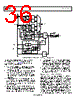
35 / 48 page  Data Sheet AD9739 Rev. B | Page 35 of 48 MULTIPLE DEVICE SYNCHRONIZATION Synchronization of multiple AD9739s requires all of the devices to have matching pipeline delays. This implies the DAC outputs are time aligned to the same phase when all devices are fed with the same data pattern at the same instance of time. The main contributor to phase ambiguity between devices is from the div-by-4 circuitry that drives the Rx data path and data controller (see Figure 53). This phase ambiguity can result in a ±2 sample offset between any two devices. Because the state of this internal divider is unknown at power-up, a synchronization method that phase aligns the digital paths of multiple AD9739s is required to ensure matching pipeline delays. Figure 52 shows a top-level diagram of multiple AD9739s synchronized to each other with sample alignment of the different data streams within the FPGA (or among multiple FPGAs) being assumed. A common RF clock source is distributed to each of the AD9739 devices via a dual clock buffer (such as the ADCLK946) with matched PCB trace lengths to each device to ensure matched propagation delays. One AD9739 is designated as the master providing a SYNC_OUT reference clock (equal to fDAC/4) to itself as well as the other AD9739 slave device’s SYNC_IN input. LVDS fanout buffers with matched output delays are again used to distribute the SYNC_OUT and DCO signals of the master to the slave devices and FPGAs, respectively, thus ensuring tight time alignment. Note, in the case of a single FPGA implementation (that is, I/Q application), the DCO of the master can drive the FPGA directly. After synchronization, the internal div-by-4 circuitry will have equal phases that drive their respective LVDS controllers. Note, the mu and data receiver controller of both devices must be configured for the same SPI register settings (that is, SET_PHS and DCI_DEL) upon SPI initialization such that controllers converge to similar delays. To validate that delays are roughly matched, the user can read back the delays of both devices (that is, MUDEL and DCI_DEL) to determine if they are in an acceptable window that accounts for slight mismatches between different devices’ delay lines. FPGA_1 MATCHED DELAYS TO FPGA_2 MASTER DCO TO OTHER FPGAs TO SLAVE_1 TO SLAVE_N MATCHED DELAYS MATCHED DELAYS 1:N LVDS REPEATER AD9739 MASTER DCO DACCLK SYNC_IN DCI SYNC_OUT COMMON CLOCK SOURCE 0.8GHz TO 2.0GHz DCO ADCLK346 1:N LVDS REPEATER AD9739 SLAVE_1 DCO DACCLK SYNC_IN DCI SYNC_OUT AD9739 SLAVE_N DCO DACCLK SYNC_IN DCI SYNC_OUT FPGA_2 Figure 52. Functional Block Diagram of Two AD9739s Synchronized |
|
链接网址 |
| ALLDATASHEET是否为您带来帮助? [ DONATE ] |
关于 Alldatasheet | 广告服务 | 联系我们 | 隐私政策 | 数据表链接 | 链接交换 | 制造商名单 All Rights Reserved©Alldatasheet.com |
| Russian : Alldatasheetru.com | Korean : Alldatasheet.co.kr | Spanish : Alldatasheet.es | French : Alldatasheet.fr | Italian : Alldatasheetit.com Portuguese : Alldatasheetpt.com | Polish : Alldatasheet.pl | Vietnamese : Alldatasheet.vn Indian : Alldatasheet.in | Mexican : Alldatasheet.com.mx | British : Alldatasheet.co.uk | New Zealand : Alldatasheet.co.nz |
|
Family Site : ic2ic.com |
icmetro.com |
 Chinese ▼
 English
 Chinese
 German
 Japanese
 Russian
 Korean
 Spanish
 French
 Italian
 Portuguese
 Polish
 Vietnamese
 Indian
 Mexican
 British
 New Zealand