|
数据搜索系统,热门电子元器件搜索 |
|
|
数据搜索系统,热门电子元器件搜索 |
|
AD9739-R2-EBZ 数据表(PDF) 45 Page - Analog Devices |
|
|
|||||||||||||||||||||||||||||
AD9739-R2-EBZ 数据表(HTML) 45 Page - Analog Devices |
|
|
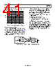
45 / 48 page  Data Sheet AD9739 Rev. B | Page 45 of 48 RECOMMENDED START-UP SEQUENCE Upon power-up of the AD9739, a host processor is required to initialize and configure the AD9739 via its SPI port. Figure 75 shows a flowchart of the sequential steps required, while Table 31 and Table 32 provides more detail on the SPI register write/read operations required to implement the flowchart steps. Note the following: • A software reset is optional because the AD9739 has both an internal POR circuit and a RESET pin. • The SYNC controller is optional because it is only required to synchronize two or more devices. If synchronization is required, validate that DCI_DEL values between devices are sufficiently matched. • The mu controller must be first enabled (and in track mode) before the data receiver controller is enabled because the DCO output signal is derived from this circuitry. • A wait period is related to fDATA periods. • Limit the number of attempts to lock the controllers to three; locks typically occur on the first attempt. • Hardware or software interrupts can be used to monitor the status of the controllers. CONFIGURE SPI PORT SOFTWARE RESET WAIT A FEW 100µs CONFIGURE MU CONT. NO YES YES YES SET CLK INPUT CMV MU CONT. LOCKED? WAIT A FEW 100µs CONFIGURE SYNC CONT. NO SYNC CONT. VALID? WAIT A FEW 100µs CONFIGURE Rx DATA CONT. NO Rx DATA CONT. LOCKED? RECONFIGURE TxDAC FROM DEFAULT SETTING COMPARE DCI_DEL VALUES SYNC. ONLY OPTIONAL Figure 75. Flowchart for Initialization and Configuration of the AD9739 |
|
链接网址 |
| ALLDATASHEET是否为您带来帮助? [ DONATE ] |
关于 Alldatasheet | 广告服务 | 联系我们 | 隐私政策 | 数据表链接 | 链接交换 | 制造商名单 All Rights Reserved©Alldatasheet.com |
| Russian : Alldatasheetru.com | Korean : Alldatasheet.co.kr | Spanish : Alldatasheet.es | French : Alldatasheet.fr | Italian : Alldatasheetit.com Portuguese : Alldatasheetpt.com | Polish : Alldatasheet.pl | Vietnamese : Alldatasheet.vn Indian : Alldatasheet.in | Mexican : Alldatasheet.com.mx | British : Alldatasheet.co.uk | New Zealand : Alldatasheet.co.nz |
|
Family Site : ic2ic.com |
icmetro.com |
 Chinese ▼
 English
 Chinese
 German
 Japanese
 Russian
 Korean
 Spanish
 French
 Italian
 Portuguese
 Polish
 Vietnamese
 Indian
 Mexican
 British
 New Zealand