|
数据搜索系统,热门电子元器件搜索 |
|
|
数据搜索系统,热门电子元器件搜索 |
|
AD9739-R2-EBZ 数据表(PDF) 42 Page - Analog Devices |
|
|
|||||||||||||||||||||||||||||
AD9739-R2-EBZ 数据表(HTML) 42 Page - Analog Devices |
|
|
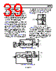
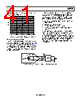
42 / 48 page  AD9739 Data Sheet Rev. B | Page 42 of 48 Output Stage Configuration The AD9739 is intended to serve high dynamic range applications that require wide signal reconstruction bandwidth (that is, DOCSIS CMTS) and/or high IF/RF signal generation. Optimum ac performance can only be realized if the DAC output is configured for differential (that is, balanced) operation with its output common-mode voltage biased to analog ground. The output network used to interface to the DAC should provide a near 0 Ω dc bias path to analog ground. Any imbalance in the output impedance between the IOUTP and IOUTN pins results in asymmetrical signal swings that degrade the distortion performance (mostly even order) and noise performance. Component selection and layout are critical in realizing the performance potential of the AD9739. MINI-CIRCUITS® TC1-33-75G+ 90Ω 90Ω IOUTP IOUTN 70Ω Figure 66. Recommended Balun for Wideband Applications with Upper Bandwidths of up to 2.2 GHz Most applications requiring balanced-to-unbalanced conversion can take advantage of the Ruthroff 1:1 balun configuration shown in Figure 66. This configuration provides excellent amplitude/phase balance over a wide frequency range while providing a 0 Ω dc bias path to each DAC output. Also, its design provides exceptional bandwidth and can be considered for applications requiring signal reconstruction of up to 2.2 GHz. The characterization plots shown in this data sheet are based on the AD9739 evaluation board, which uses this configuration. Figure 67 compares the measured frequency response for normal and mix mode using the AD9739 evaluation board vs. the ideal frequency response. –36 –33 –30 –27 –24 –21 –18 –15 –12 –9 –6 –3 0 0 500 1000 1500 2000 2500 3000 3500 FREQUENCY (MHz) IDEAL BASEBAND MODE MIX MODE TC1-33-75G BASEBAND TC1-33-75G IDEAL MIX MODE Figure 67. Measured vs. Ideal Frequency Response for Normal (Baseband) and Mix Mode Operation Using a TC1-33-75G Transformer on the AD9739 Evaluation Board Figure 68 shows an interface that can be considered when interfacing the DAC output to a self-biased differential gain block. The inductors shown serve as RF chokes (L) that provide the dc bias path to analog ground. The value of the inductor, along with the dc blocking capacitors (C), determines the lower cutoff frequency of the composite pass-band response. An RF balun should also be considered before the RF differential gain stage and any filtering to ensure symmetrical common-mode impedance seen by the DAC output while suppressing any common-mode noise, harmonics, and clock spurs prior to amplification. 90Ω IOUTP IOUTN 70Ω L L RF DIFF AMP C C OPTIONAL BALUN AND FILTER 90Ω LPF Figure 68. Interfacing the DAC Output to the Self-Biased Differential Gain Stage For applications operating the AD9739 in mix mode with output frequencies extending beyond 2.2 GHz, the circuits shown in Figure 69 should be considered. The circuit in Figure 69 uses a wideband balun with a configuration similar to the one shown in Figure 68 to provide a dc bias path for the DAC outputs. The circuit in Figure 70 takes advantage of ceramic chip baluns to provide a dc bias path for the DAC outputs while providing excellent amplitude/phase balance over a narrower RF band. These low cost, low insertion loss baluns are available for different popular RF bands and provide excellent amplitude/ phase balance over their specified frequency range. C C MINI-CIRCUITS TC1-1-462M 90Ω IOUTP IOUTN 70Ω L L 90Ω Figure 69. Recommended Mix Mode Configuration Offering Extended RF Bandwidth Using a TC1-1-43A+ Balun MURATA JOHANSON TECHNOLOGY CHIP BALUNS 180Ω IOUTP IOUTN 70Ω Figure 70. Lowest Cost and Size Configuration for Narrow RF Band Operation |
|
链接网址 |
| ALLDATASHEET是否为您带来帮助? [ DONATE ] |
关于 Alldatasheet | 广告服务 | 联系我们 | 隐私政策 | 数据表链接 | 链接交换 | 制造商名单 All Rights Reserved©Alldatasheet.com |
| Russian : Alldatasheetru.com | Korean : Alldatasheet.co.kr | Spanish : Alldatasheet.es | French : Alldatasheet.fr | Italian : Alldatasheetit.com Portuguese : Alldatasheetpt.com | Polish : Alldatasheet.pl | Vietnamese : Alldatasheet.vn Indian : Alldatasheet.in | Mexican : Alldatasheet.com.mx | British : Alldatasheet.co.uk | New Zealand : Alldatasheet.co.nz |
|
Family Site : ic2ic.com |
icmetro.com |
 Chinese ▼
 English
 Chinese
 German
 Japanese
 Russian
 Korean
 Spanish
 French
 Italian
 Portuguese
 Polish
 Vietnamese
 Indian
 Mexican
 British
 New Zealand