|
数据搜索系统,热门电子元器件搜索 |
|
|
数据搜索系统,热门电子元器件搜索 |
|
PCMB065T-R68MS 数据表(PDF) 19 Page - International Rectifier |
|
|
|||||||||||||||||||||||||||||
PCMB065T-R68MS 数据表(HTML) 19 Page - International Rectifier |
|
|
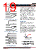
19 / 46 page  - 19 - JANURARY 18, 2013 | DATA SHEET | Rev 3.5 19 IR3898 6A Highly Integrated SupIRBuck TM Single-Input Voltage, Synchronous Buck Regulator PD-97662 Pvin(12V) Vcc Intl_SS Enable >1.2V Vp>1V Figure 5a: Recommended startup for Normal operation Pvin (12V) Vcc Enable> 1. 2 V Intl_SS Vp Figure 5b: Recommended startup for sequencing operation (ratiometric or simultaneous) Pvin=Vin=12V Vp=VDDQ/2 Vcc Vref=0 Enable > 1.2V VTT VDDQ VTT Tracking Figure 5c: Recommended startup for memory tracking operation (VTT-DDR4) Figure 5a shows the recommended start-up sequence for the normal (non-tracking, non-sequencing) operation of IR3898, when Enable is used as logic input. Figure 5b shows the recommended startup sequence for sequenced operation of IR3898 with Enable used as logic input. Figure 5c shows the recommended startup sequence for tracking operation of IR3898 with Enable used as logic input. In normal and sequencing mode operation, Vref is left floating. A 100pF ceramic capacitor is recommended between this pin and Gnd. In tracking mode operation, Vref should be tied to Gnd. It is recommended to apply the Enable signal after the VCC voltage has been established. If the Enable signal is present before VCC, a 50kΩ resistor can be used in series with the Enable pin to limit the current flowing into the Enable pin. PRE-BIAS STARTUP IR3898 is able to start up into pre-charged output, which prevents oscillation and disturbances of the output voltage. The output starts in asynchronous fashion and keeps the synchronous MOSFET (Sync FET) off until the first gate signal for control MOSFET (Ctrl FET) is generated. Figure 6a shows a typical Pre-Bias condition at start up. The sync FET always starts with a narrow pulse width (12.5% of a switching period) and gradually increases its duty cycle with a step of 12.5% until it reaches the steady state value. The number of these startup pulses for each step is 16 and it’s internally programmed. Figure 6b shows the series of 16x8 startup pulses. Vo [V] [Time] Pre-Bias Voltage Figure 6a: Pre-Bias startup ... ... ... HDRv ... ... ... 16 End of PB LDRv 12.5% 25% 87.5% 16 ... ... ... ... Figure 6b: Pre-Bias startup pulses |
|
链接网址 |
| ALLDATASHEET是否为您带来帮助? [ DONATE ] |
关于 Alldatasheet | 广告服务 | 联系我们 | 隐私政策 | 数据表链接 | 链接交换 | 制造商名单 All Rights Reserved©Alldatasheet.com |
| Russian : Alldatasheetru.com | Korean : Alldatasheet.co.kr | Spanish : Alldatasheet.es | French : Alldatasheet.fr | Italian : Alldatasheetit.com Portuguese : Alldatasheetpt.com | Polish : Alldatasheet.pl | Vietnamese : Alldatasheet.vn Indian : Alldatasheet.in | Mexican : Alldatasheet.com.mx | British : Alldatasheet.co.uk | New Zealand : Alldatasheet.co.nz |
|
Family Site : ic2ic.com |
icmetro.com |
 Chinese ▼
 English
 Chinese
 German
 Japanese
 Russian
 Korean
 Spanish
 French
 Italian
 Portuguese
 Polish
 Vietnamese
 Indian
 Mexican
 British
 New Zealand