|
数据搜索系统,热门电子元器件搜索 |
|
|
数据搜索系统,热门电子元器件搜索 |
|
PCMB065T-R68MS 数据表(PDF) 44 Page - International Rectifier |
|
|
|||||||||||||||||||||||||||||
PCMB065T-R68MS 数据表(HTML) 44 Page - International Rectifier |
|
|
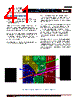
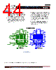
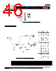
44 / 46 page  - 44 - JANURARY 18, 2013 | DATA SHEET | Rev 3.5 44 IR3898 6A Highly Integrated SupIRBuck TM Single-Input Voltage, Synchronous Buck Regulator PD-97662 SOLDER RESIST IR recommends that the larger Power or Land Area pads are Solder Mask Defined (SMD.) This allows the underlying Copper traces to be as large as possible, which helps in terms of current carrying capability and device cooling capability. When using SMD pads, the underlying copper traces should be at least 0.05mm larger (on each edge) than the Solder Mask window, in order to accommodate any layer to layer misalignment. (i.e. 0.1mm in X & Y.) However, for the smaller Signal type leads around the edge of the device, IR recommends that these are Non Solder Mask Defined or Copper Defined. When using NSMD pads, the Solder Resist Window should be larger than the Copper Pad by at least 0.025mm on each edge, (i.e. 0.05mm in X&Y,) in order to accommodate any layer to layer misalignment. Ensure that the solder resist in-between the smaller signal lead areas are at least 0.15mm wide, due to the high x/y aspect ratio of the solder mask strip. Figure 51: Solder resist * Contact International Rectifier to receive an electronic PCB Library file in your preferred format |
|
链接网址 |
| ALLDATASHEET是否为您带来帮助? [ DONATE ] |
关于 Alldatasheet | 广告服务 | 联系我们 | 隐私政策 | 数据表链接 | 链接交换 | 制造商名单 All Rights Reserved©Alldatasheet.com |
| Russian : Alldatasheetru.com | Korean : Alldatasheet.co.kr | Spanish : Alldatasheet.es | French : Alldatasheet.fr | Italian : Alldatasheetit.com Portuguese : Alldatasheetpt.com | Polish : Alldatasheet.pl | Vietnamese : Alldatasheet.vn Indian : Alldatasheet.in | Mexican : Alldatasheet.com.mx | British : Alldatasheet.co.uk | New Zealand : Alldatasheet.co.nz |
|
Family Site : ic2ic.com |
icmetro.com |
 Chinese ▼
 English
 Chinese
 German
 Japanese
 Russian
 Korean
 Spanish
 French
 Italian
 Portuguese
 Polish
 Vietnamese
 Indian
 Mexican
 British
 New Zealand