|
数据搜索系统,热门电子元器件搜索 |
|
|
数据搜索系统,热门电子元器件搜索 |
|
PCMB065T-R68MS 数据表(PDF) 26 Page - International Rectifier |
|
|
|||||||||||||||||||||||||||||
PCMB065T-R68MS 数据表(HTML) 26 Page - International Rectifier |
|
|
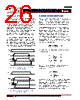
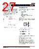
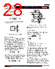
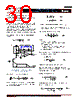
26 / 46 page  - 26 - JANURARY 18, 2013 | DATA SHEET | Rev 3.5 26 IR3898 6A Highly Integrated SupIRBuck TM Single-Input Voltage, Synchronous Buck Regulator PD-97662 SOFT-STOP (S_CTRL) Soft-stop function can make output voltage discharge gradually. To enable this function, S_Ctrl is kept low first when EN goes high. Then S_Ctrl is pulled high to cross the logic level threshold (typ. 2V), the internal soft-start ramp is initiated. So Vo follows Intl_SS to ramp up until it reaches its steady state. In soft-stop process, S_Ctrl needs to be pulled low before EN goes low. After S_Ctrl goes below its threshold, a decreasing ramp is generated at Intl_SS with the same slope as in soft-start ramp. Vo follows this ramp to discharge softly until shutdown completely. Figure 19 shows the timing diagram of S_Ctrl controlled soft-start and soft-stop. If the falling edge of Enable signal asserts before S_Ctrl falling edge, the converter is still turned off by Enable. Both gate drivers are turned off immediately and Vo discharges to zero. Figure 20 shows the timing diagram of Enable controlled soft-start and soft-stop. Soft stop feature ensures that Vout discharges and also regulates the current precisely to zero with no undershoot. 0 0 0 Intl _SS S_Ctrl Vout 0 Enable 0.15V 0.65V 0.15V 0.65V Figure 19: Timing Diagram for S_Ctrl controlled Soft Start/Soft Stop 0 0 0 Intl _SS S_Ctrl Vout 0.15V 0 Enable 1.2V 1.0V 0.65V Figure 20: Timing Diagram for Enable controlled Soft Start/Shutdown MINIMUM ON TIME CONSIDERATIONS The minimum ON time is the shortest amount of time for Ctrl FET to be reliably turned on. This is very critical parameter for low duty cycle, high frequency applications. Conventional approach limits the pulse width to prevent noise, jitter and pulse skipping. This results to lower closed loop bandwidth. IR has developed a proprietary scheme to improve and enhance minimum pulse width which utilizes the benefits of voltage mode control scheme with higher switching frequency, wider conversion ratio and higher closed loop bandwidth, the latter results in reduction of output capacitors. Any design or application using IR3898 must ensure operation with a pulse width that is higher than this minimum on-time and preferably higher than 60 ns. This is necessary for the circuit to operate without jitter and pulse-skipping, which can cause high inductor current ripple and high output voltage ripple. in (3) V out on ss V D t FF In any application that uses IR3898, the following condition must be satisfied: (min) (min) (min) (4) (5) (6) on on out on in s out in s on tt V t VF V VF t The minimum output voltage is limited by the reference voltage and hence Vout(min) = 0.5 V. Therefore, for Vout(min) = 0.5 V, V/uS 33 . 8 ns 60 V 0.5 V V in (min) (min) in s on out s F t V F Therefore, at the maximum recommended input voltage 21V and minimum output voltage, the converter should be designed at a switching frequency that does not exceed 396 kHz. Conversely, for operation at the maximum recommended operating frequency (1.65 MHz) and minimum output voltage (0.5V). The input voltage (PVin) should not exceed 5.05V, otherwise pulse skipping will happen. |
|
链接网址 |
| ALLDATASHEET是否为您带来帮助? [ DONATE ] |
关于 Alldatasheet | 广告服务 | 联系我们 | 隐私政策 | 数据表链接 | 链接交换 | 制造商名单 All Rights Reserved©Alldatasheet.com |
| Russian : Alldatasheetru.com | Korean : Alldatasheet.co.kr | Spanish : Alldatasheet.es | French : Alldatasheet.fr | Italian : Alldatasheetit.com Portuguese : Alldatasheetpt.com | Polish : Alldatasheet.pl | Vietnamese : Alldatasheet.vn Indian : Alldatasheet.in | Mexican : Alldatasheet.com.mx | British : Alldatasheet.co.uk | New Zealand : Alldatasheet.co.nz |
|
Family Site : ic2ic.com |
icmetro.com |
 Chinese ▼
 English
 Chinese
 German
 Japanese
 Russian
 Korean
 Spanish
 French
 Italian
 Portuguese
 Polish
 Vietnamese
 Indian
 Mexican
 British
 New Zealand