|
数据搜索系统,热门电子元器件搜索 |
|
|
数据搜索系统,热门电子元器件搜索 |
|
PCMB065T-R68MS 数据表(PDF) 27 Page - International Rectifier |
|
|
|||||||||||||||||||||||||||||
PCMB065T-R68MS 数据表(HTML) 27 Page - International Rectifier |
|
|
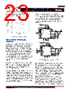
27 / 46 page  - 27 - JANURARY 18, 2013 | DATA SHEET | Rev 3.5 27 IR3898 6A Highly Integrated SupIRBuck TM Single-Input Voltage, Synchronous Buck Regulator PD-97662 MAXIMUM DUTY RATIO A certain off-time is specified for IR3898. This provides an upper limit on the operating duty ratio at any given switching frequency. The off-time remains at a relatively fixed ratio to switching period in low and mid frequency range, while in high frequency range this ratio increases, thus the lower the maximum duty ratio at which IR3898 can operate. Figure 21 shows a plot of the maximum duty ratio vs. the switching frequency with built in input voltage feed forward mechanism. Figure 21: Maximum duty cycle vs. switching frequency. DESIGN EXAMPLE The following example is a typical application for IR3898. The application circuit is shown in Fig.28. = =12 V ( 10%) =1 2 V = 6 A Ripple Voltage= 1% * 5% * 50% =600 kHz in o o o oo s V V. I V ΔV V load transient F ( for ) Enabling the IR3898 As explained earlier, the precise threshold of the Enable lends itself well to implementation of a UVLO for the Bus Voltage as shown in Fig. 22. IR3898 Enable Vin R1 R2 Figure 22: Using Enable pin for UVLO implementation For a typical Enable threshold of VEN = 1.2 V 2 (min) 12 * 1.2 (7) in EN R V V RR 21 min (8) EN in( ) EN V RR VV For Vin (min)=9.2V, R1=49.9K and R2=7.5K ohm is a good choice. Programming the frequency For Fs = 600 kHz, select Rt = 39.2 KΩ, using Table 1. Output Voltage Programming Output voltage is programmed by reference voltage and external voltage divider. The Fb pin is the inverting input of the error amplifier, which is internally referenced to 0.5V. The divider ratio is set to provide 0.5V at the Fb pin when the output is at its desired value. The output voltage is defined by using the following equation: |
|
链接网址 |
| ALLDATASHEET是否为您带来帮助? [ DONATE ] |
关于 Alldatasheet | 广告服务 | 联系我们 | 隐私政策 | 数据表链接 | 链接交换 | 制造商名单 All Rights Reserved©Alldatasheet.com |
| Russian : Alldatasheetru.com | Korean : Alldatasheet.co.kr | Spanish : Alldatasheet.es | French : Alldatasheet.fr | Italian : Alldatasheetit.com Portuguese : Alldatasheetpt.com | Polish : Alldatasheet.pl | Vietnamese : Alldatasheet.vn Indian : Alldatasheet.in | Mexican : Alldatasheet.com.mx | British : Alldatasheet.co.uk | New Zealand : Alldatasheet.co.nz |
|
Family Site : ic2ic.com |
icmetro.com |
 Chinese ▼
 English
 Chinese
 German
 Japanese
 Russian
 Korean
 Spanish
 French
 Italian
 Portuguese
 Polish
 Vietnamese
 Indian
 Mexican
 British
 New Zealand