|
数据搜索系统,热门电子元器件搜索 |
|
|
数据搜索系统,热门电子元器件搜索 |
|
PCMB065T-R68MS 数据表(PDF) 20 Page - International Rectifier |
|
|
|||||||||||||||||||||||||||||
PCMB065T-R68MS 数据表(HTML) 20 Page - International Rectifier |
|
|
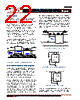
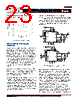
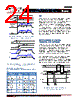
20 / 46 page  - 20 - JANURARY 18, 2013 | DATA SHEET | Rev 3.5 20 IR3898 6A Highly Integrated SupIRBuck TM Single-Input Voltage, Synchronous Buck Regulator PD-97662 SOFT-START IR3898 has an internal digital soft-start to control the output voltage rise and to limit the current surge at the start-up. To ensure correct start-up, the soft-start sequence initiates when the Enable and Vcc rise above their UVLO thresholds and generate the Power On Ready (POR) signal. The internal soft-start (Intl_SS) signal linearly rises with the rate of 0.2mV/µs from 0V to 1.5V. Figure 7 shows the waveforms during soft start (also refer to Fig. 20). The normal Vout start-up time is fixed, and is equal to: 0.65V-0.15V 2.5ms (1) 0.2mV/ s start T During the soft start the over-current protection (OCP) and over-voltage protection (OVP) is enabled to protect the device for any short circuit or over voltage condition. POR Intl_SS Vout 0.15V 0.65V t 1 t 2 t3 1.5V 3.0V Figure 7: Theoretical operation waveforms during soft-start (non tracking / non sequencing) OPERATING FREQUENCY The switching frequency can be programmed between 300kHz – 1500kHz by connecting an external resistor from Rt pin to Gnd. Table 1 tabulates the oscillator frequency versus Rt. SHUTDOWN IR3898 can be shut down by pulling the Enable pin below its 1.0V threshold. This will tri-state both the high side and the low side driver. TABLE 1: SWITCHING FREQUENCY (FS) VS. EXTERNAL RESISTOR (R T) Rt (KΩ) Freq (KHz) 80.6 300 60.4 400 48.7 500 39.2 600 34 700 29.4 800 26.1 900 23.2 1000 21 1100 19.1 1200 17.4 1300 16.2 1400 15 1500 OVER CURRENT PROTECTION The over current (OC) protection is performed by sensing current through the RDS(on) of the Synchronous MOSFET. This method enhances the converter’s efficiency, reduces cost by eliminating a current sense resistor and any layout related noise issues. The current limit is pre-set internally and is compensated according to the IC temperature. So at different ambient temperature, the over-current trip threshold remains almost constant. Note that the over current limit is a function of the Vcc voltage. Refer to the typical performance curves of the OCP current limit with the internal LDO and the external Vcc voltage. Detailed operation of OCP is explained as follows. Over Current Protection circuit senses the inductor current flowing through the Synchronous MOSFET closer to the valley point. OCP circuit samples this current for 40nsec typically after the rising edge of the PWM set pulse which has a width of 12.5% of the switching period.The PWM pulse starts at the falling edge of the PWM set pulse.This makes valley current sense more robust as current is sensed close to the bottom of the inductor downward slope where transient and switching noise are lower and helps to prevent false tripping due to noise and transient. An OC condition is detected if the load current exceeds the threshold, the converter enters into hiccup mode. PGood will go low and the internal soft start signal will be pulled low. The converter goes into hiccup mode with a 20.48ms (typ.) delay as shown in Figure 8. The convertor stays in this mode until the over load or short circuit is removed. The actual DC output current limit point will be greater |
|
链接网址 |
| ALLDATASHEET是否为您带来帮助? [ DONATE ] |
关于 Alldatasheet | 广告服务 | 联系我们 | 隐私政策 | 数据表链接 | 链接交换 | 制造商名单 All Rights Reserved©Alldatasheet.com |
| Russian : Alldatasheetru.com | Korean : Alldatasheet.co.kr | Spanish : Alldatasheet.es | French : Alldatasheet.fr | Italian : Alldatasheetit.com Portuguese : Alldatasheetpt.com | Polish : Alldatasheet.pl | Vietnamese : Alldatasheet.vn Indian : Alldatasheet.in | Mexican : Alldatasheet.com.mx | British : Alldatasheet.co.uk | New Zealand : Alldatasheet.co.nz |
|
Family Site : ic2ic.com |
icmetro.com |
 Chinese ▼
 English
 Chinese
 German
 Japanese
 Russian
 Korean
 Spanish
 French
 Italian
 Portuguese
 Polish
 Vietnamese
 Indian
 Mexican
 British
 New Zealand