|
数据搜索系统,热门电子元器件搜索 |
|
|
数据搜索系统,热门电子元器件搜索 |
|
PCMB065T-R68MS 数据表(PDF) 21 Page - International Rectifier |
|
|
|||||||||||||||||||||||||||||
PCMB065T-R68MS 数据表(HTML) 21 Page - International Rectifier |
|
|
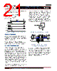
21 / 46 page  - 21 - JANURARY 18, 2013 | DATA SHEET | Rev 3.5 21 IR3898 6A Highly Integrated SupIRBuck TM Single-Input Voltage, Synchronous Buck Regulator PD-97662 than the valley point by an amount equal to approximately half of peak to peak inductor ripple current. (2) 2 OCP i I ILIMIT IOCP= DC current limit hiccup point ILIMIT= Current limit Valley Point Δi=Inductor ripple current 0 IL 0 HDrv Current Limit 0 LDrv ... ... 0 PGood 20.48ms Hiccup Figure 8: Timing Diagram for Current Limit and Hiccup THERMAL SHUTDOWN Temperature sensing is provided inside IR3898. The trip threshold is typically set to 145 oC. When trip threshold is exceeded, thermal shutdown turns off both MOSFETs and resets the internal soft start. Automatic restart is initiated when the sensed temperature drops within the operating range. There is a 20 oC hysteresis in the thermal shutdown threshold. EXTERNAL SYNCHRONIZATION IR3898 incorporates an internal phase lock loop (PLL) circuit which enables synchronization of the internal oscillator to an external clock. This function is important to avoid sub-harmonic oscillations due to beat frequency for embedded systems when multiple point-of-load (POL) regulators are used. A multi-function pin, Rt/Sync, is used to connect the external clock. If the external clock is present before the converter turns on, Rt/Sync pin can be connected to the external clock signal solely and no other resistor is needed. If the external clock is applied after the converter turns on, or the converter switching frequency needs to toggle between the external clock frequency and the internal free-running frequency, an external resistor from Rt/Sync pin to Gnd is required to set the free-running frequency. When an external clock is applied to Rt/Sync pin after the converter runs in steady state with its free-running frequency, a transition from the free-running frequency to the external clock frequency will happen. This transition is to gradually make the actual switching frequency equal to the external clock frequency, no matter which one is higher. On the contrary, when the external clock signal is removed from Rt/Sync pin, the switching frequency is also changed to free-running gradually. In order to minimize the impact from these transitions to output voltage, a diode is recommended to add between the external clock and Rt/Sync pin as shown in Figure 9a. Figure 9b shows the timing diagram of these transitions. IR3898 Rt/Sync Gnd Figure 9a: Configuration of External Synchronization SW SYNC ... ... Gradually change Fs1 Fs2 Fs1 Free Running Frequency Synchronize to the external clock Return to free- running freq Gradually change Figure 9b: Timing Diagram for Synchronization to the external clock (Fs1>Fs2 or Fs1<Fs2) An internal circuit is used to change the PWM ramp slope according to the clock frequency applied on Rt/Sync pin. Even though the frequency of the external synchronization clock can vary in a wide range, the PLL circuit will make sure that the ramp amplitude is kept constant, requiring no adjustment of the loop compensation. Vin variation also affects the ramp amplitude, which will be discussed separately in Feed-Forward section. |
|
链接网址 |
| ALLDATASHEET是否为您带来帮助? [ DONATE ] |
关于 Alldatasheet | 广告服务 | 联系我们 | 隐私政策 | 数据表链接 | 链接交换 | 制造商名单 All Rights Reserved©Alldatasheet.com |
| Russian : Alldatasheetru.com | Korean : Alldatasheet.co.kr | Spanish : Alldatasheet.es | French : Alldatasheet.fr | Italian : Alldatasheetit.com Portuguese : Alldatasheetpt.com | Polish : Alldatasheet.pl | Vietnamese : Alldatasheet.vn Indian : Alldatasheet.in | Mexican : Alldatasheet.com.mx | British : Alldatasheet.co.uk | New Zealand : Alldatasheet.co.nz |
|
Family Site : ic2ic.com |
icmetro.com |
 Chinese ▼
 English
 Chinese
 German
 Japanese
 Russian
 Korean
 Spanish
 French
 Italian
 Portuguese
 Polish
 Vietnamese
 Indian
 Mexican
 British
 New Zealand