|
数据搜索系统,热门电子元器件搜索 |
|
|
数据搜索系统,热门电子元器件搜索 |
|
TMS320C31PQL60 数据表(PDF) 39 Page - Texas Instruments |
|
|
|||||||||||||||||||||||||||||
TMS320C31PQL60 数据表(HTML) 39 Page - Texas Instruments |
|
|
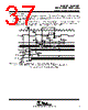
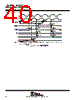
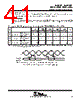
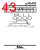
39 / 48 page  HOLD timing HOLD is an asynchronous input that can be asserted at any time during a clock cycle. If the specified timings are met, the exact sequence shown in Figure 27 occurs; otherwise, an additional delay of one clock cycle is possible. The table, “timing parameters for HOLD / HOLDA”, defines the timing parameters for the HOLD and HOLDA signals. The numbers shown in Figure 27 correspond with those in the NO. column of the table. The NOHOLD bit of the primary-bus control register overrides the HOLD signal. When this bit is set, the device comes out of hold and prevents future hold cycles. Asserting HOLD prevents the processor from accessing the primary bus. Program execution continues until a read from or a write to the primary bus is requested. In certain circumstances, the first write is pending, thus allowing the processor to continue until a second write is encountered. timing parameters for HOLD/HOLDA (see Figure 27) NO. ’LC31-33 ’C31-40 ’LC31-40 ’C31-50 ’C31-60 ’C31-80 UNIT MIN MAX MIN MAX MIN MAX MIN MAX MIN MAX 69 tsu(HOLD-H1L) Setup time, HOLD before H1 low 15 13 10 8 5 ns 70 tv(H1L-HOLDA) Valid time, HOLDA after H1 low 0† 10 0† 9 0† 7 0† 6 0† 5 ns 71 tw(HOLD)‡ Pulse duration, HOLD low 2tc(H) 2tc(H) 2tc(H) 2tc(H) 2tc(H) ns 72 tw(HOLDA) Pulse duration, HOLDA low tcH–5† tcH–5† tcH –5† tcH –5† tcH–5† ns 73 td(H1L-SH)H Delay time, H1 low to STRB high for a HOLD 0§ 10 0§ 9 0§ 7 0§ 6 0§ 4 ns 74 tdis(H1L-S) Disable time, H1 low to STRB to the high-impedance state 0§ 10† 0§ 9† 0§ 8† 0§ 7† 0§ 7† ns 75 ten(H1L-S) Enable time, H1 low to STRB enabled (active) 0§ 10 0§ 9 0§ 7 0§ 6 0§ 6 ns 76 tdis(H1L-RW) Disable time, H1 low to R/W to the high-impedance state 0† 10† 0† 9† 0† 8† 0† 7† 0† 6† ns 77 ten(H1L-RW) Enable time, H1 low to R/W enabled (active) 0† 10 0† 9 0† 7 0† 6 0† 6 ns 78 tdis(H1L-A) Disable time, H1 low to address to the high-impedance state 0§ 10† 0§ 10† 0§ 8† 0§ 7† 0§ 7† ns 79 ten(H1L-A) Enable time, H1 low to address enabled (valid) 0§ 15 0§ 13 0§ 12 0§ 11 0§ 10 ns 80 tdis(H1H-D) Disable time, H1 high to data to the high-impedance state 0§ 10† 0§ 9† 0§ 8† 0§ 7† 0§ 6† ns † This value is characterized but not tested ‡ HOLD is an asynchronous input and can be asserted at any point during a clock cycle. If the specified timings are met, the exact sequence shown in Figure 27 occurs; otherwise, an additional delay of one clock cycle is possible. § Not tested |
|
链接网址 |
| ALLDATASHEET是否为您带来帮助? [ DONATE ] |
关于 Alldatasheet | 广告服务 | 联系我们 | 隐私政策 | 数据表链接 | 链接交换 | 制造商名单 All Rights Reserved©Alldatasheet.com |
| Russian : Alldatasheetru.com | Korean : Alldatasheet.co.kr | Spanish : Alldatasheet.es | French : Alldatasheet.fr | Italian : Alldatasheetit.com Portuguese : Alldatasheetpt.com | Polish : Alldatasheet.pl | Vietnamese : Alldatasheet.vn Indian : Alldatasheet.in | Mexican : Alldatasheet.com.mx | British : Alldatasheet.co.uk | New Zealand : Alldatasheet.co.nz |
|
Family Site : ic2ic.com |
icmetro.com |
 Chinese ▼
 English
 Chinese
 German
 Japanese
 Russian
 Korean
 Spanish
 French
 Italian
 Portuguese
 Polish
 Vietnamese
 Indian
 Mexican
 British
 New Zealand