|
数据搜索系统,热门电子元器件搜索 |
|
|
数据搜索系统,热门电子元器件搜索 |
|
TMS320C31PQL60 数据表(PDF) 26 Page - Texas Instruments |
|
|
|||||||||||||||||||||||||||||
TMS320C31PQL60 数据表(HTML) 26 Page - Texas Instruments |
|
|
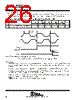
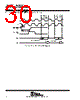
26 / 48 page  TMS320C31, TMS320LC31 DIGITAL SIGNAL PROCESSORS SPRS035B – MARCH 1996 – REVISED JANUARY 1999 26 POST OFFICE BOX 1443 • HOUSTON, TEXAS 77251–1443 changing XFx from an input to an output The following table defines the timing parameter for changing the XFx pin from an input pin to an output pin. The number shown in Figure 20 corresponds with the number in the NO. column of the table below. timing parameters of XFx changing from input to output mode (see Figure 20) NO. ’LC31-33 ’C31-40 ’LC31-40 ’C31-50 ’C31-60 ’C31-80 UNIT MIN MAX MIN MAX MIN MAX MIN MAX MIN MAX 37 td(H3H-XFIO) Delay time, H3 high to XFx switching from input to output 20 17 17 16 9 ns Execution of Load of IOF 37 H3 H1 I / OxFx Bit (see Note A) XFx Pin NOTE A: I / OxFx represents either bit 1 or bit 5 of the IOF register. Figure 20. Timing for Change of XFx From Input to Output Mode reset timing RESET is an asynchronous input that can be asserted at any time during a clock cycle. If the specified timings are met, the exact sequence shown in Figure 21 occurs; otherwise, an additional delay of one clock cycle is possible. The asynchronous reset signals include XF0/1, CLKX0, DX0, FSX0, CLKR0, DR0, FSR0, and TCLK0/1. The following table defines the timing parameters for the RESET signal. The numbers shown in Figure 21 correspond with those in the NO. column of the following table. Resetting the device initializes the bus control register to seven software wait states and therefore results in slow external accesses until these registers are initialized. HOLD is an asynchronous input and can be asserted during reset. |
|
链接网址 |
| ALLDATASHEET是否为您带来帮助? [ DONATE ] |
关于 Alldatasheet | 广告服务 | 联系我们 | 隐私政策 | 数据表链接 | 链接交换 | 制造商名单 All Rights Reserved©Alldatasheet.com |
| Russian : Alldatasheetru.com | Korean : Alldatasheet.co.kr | Spanish : Alldatasheet.es | French : Alldatasheet.fr | Italian : Alldatasheetit.com Portuguese : Alldatasheetpt.com | Polish : Alldatasheet.pl | Vietnamese : Alldatasheet.vn Indian : Alldatasheet.in | Mexican : Alldatasheet.com.mx | British : Alldatasheet.co.uk | New Zealand : Alldatasheet.co.nz |
|
Family Site : ic2ic.com |
icmetro.com |
 Chinese ▼
 English
 Chinese
 German
 Japanese
 Russian
 Korean
 Spanish
 French
 Italian
 Portuguese
 Polish
 Vietnamese
 Indian
 Mexican
 British
 New Zealand