|
数据搜索系统,热门电子元器件搜索 |
|
|
数据搜索系统,热门电子元器件搜索 |
|
TMS320C31PQL60 数据表(PDF) 6 Page - Texas Instruments |
|
|
|||||||||||||||||||||||||||||
TMS320C31PQL60 数据表(HTML) 6 Page - Texas Instruments |
|
|
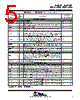
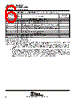
6 / 48 page  TMS320C31, TMS320LC31 DIGITAL SIGNAL PROCESSORS SPRS035B – MARCH 1996 – REVISED JANUARY 1999 6 POST OFFICE BOX 1443 • HOUSTON, TEXAS 77251–1443 TMS320C31 and TMS320LC31 Terminal Functions (Continued) TERMINAL TYPE† DESCRIPTION CONDITIONS WHEN NAME QTY TYPE† DESCRIPTION WHEN SIGNAL IS Z TYPE‡ SUPPLY AND OSCILLATOR SIGNALS H1 1 O/Z External H1 clock. H1 has a period equal to twice CLKIN. S H3 1 O/Z External H3 clock. H3 has a period equal to twice CLKIN. S VDD 20 I 5-V supply for ’C31 devices and 3.3-V supply for ’LC31 devices. All must be connected to a common supply plane.§ VSS 25 I Ground. All grounds must be connected to a common ground plane. X1 1 O Output from the internal-crystal oscillator. If a crystal is not used, X1 should be left unconnected. X2 / CLKIN 1 I Internal-oscillator input from a crystal or a clock RESERVED¶ EMU2 – EMU0 3 I Reserved for emulation. Use pullup resistors to VDD EMU3 1 O/Z Reserved for emulation S † I = input, O = output, Z = high-impedance state ‡ S = SHZ active, H = HOLD active, R = RESET active § Recommended decoupling capacitor value is 0.1 µF. ¶ Follow the connections specified for the reserved pins. Use 18 -k Ω–22-kΩ pullup resistors for best results. All VDD supply pins must be connected to a common supply plane, and all ground pins must be connected to a common ground plane. NOTES: 1. A test mode for measuring leakage currents in the TMS320C31 is implemented. This test mode powers down the clock oscillator circuit resulting in currents below 10 µA. The test mode is entered by asserting SHZ low, which tri–states all output pins and then holds both H1 and H3 at logic high. The test mode is not intended for application use because it does not preserve the processor state. 2. Since SHZ is a synchronized input and the clock is disabled, exiting the test mode occurs only when at least one of the H1/H3 pins is pulled low. Reset cannot be used to wake up in test mode since the SHZ pin is sampled and the clocks are not running. 3. On power up, the processor can be in an indeterminate state. If the state is SHZ mode and H1 and H3 are both held logic high by pull–ups, then shutdown will occur. Normally, if H1 and H3 do not have pull–ups, the rise time lag due to capacitive loading on a tri–state pin is enough to ensure a clean start. However, a slowly rising supply and board leakages to VCC may be enough to cause a bad start. Therefore, a pulldown resistor on either H1 or H3 is recommended for proper wakeup. |
|
链接网址 |
| ALLDATASHEET是否为您带来帮助? [ DONATE ] |
关于 Alldatasheet | 广告服务 | 联系我们 | 隐私政策 | 数据表链接 | 链接交换 | 制造商名单 All Rights Reserved©Alldatasheet.com |
| Russian : Alldatasheetru.com | Korean : Alldatasheet.co.kr | Spanish : Alldatasheet.es | French : Alldatasheet.fr | Italian : Alldatasheetit.com Portuguese : Alldatasheetpt.com | Polish : Alldatasheet.pl | Vietnamese : Alldatasheet.vn Indian : Alldatasheet.in | Mexican : Alldatasheet.com.mx | British : Alldatasheet.co.uk | New Zealand : Alldatasheet.co.nz |
|
Family Site : ic2ic.com |
icmetro.com |
 Chinese ▼
 English
 Chinese
 German
 Japanese
 Russian
 Korean
 Spanish
 French
 Italian
 Portuguese
 Polish
 Vietnamese
 Indian
 Mexican
 British
 New Zealand