|
数据搜索系统,热门电子元器件搜索 |
|
|
数据搜索系统,热门电子元器件搜索 |
|
EM357-RTR 数据表(PDF) 142 Page - List of Unclassifed Manufacturers |
|
|
|||||||||||||||||||||||||||||
EM357-RTR 数据表(HTML) 142 Page - List of Unclassifed Manufacturers |
|
|
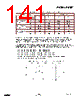
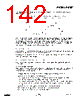
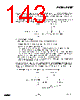
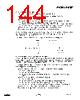
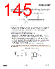
142 / 240 page  EM351 / EM357 Figure 9-26 gives an example of counter behavior when IC1FP1 polarity is inverted (same configuration as above except TIM_CC1P = 1). Figure 9-26. Example of Encoder Interface Mode with IC1FP1 Polarity Inverted The timer configured in encoder interface mode provides information on a sensor’s current position. To obtain dynamic information (speed, acceleration/deceleration), measure the period between two encoder events using a second timer configured in capture mode. The output of the encoder that indicates the mechanical zero can be used for this purpose. Depending on the time between two events, the counter can also be read at regular times. Do this by latching the counter value into a third input capture register. (In this case the capture signal must be periodic and can be generated by another timer). 9.3.12 Timer Input XOR Function The TIM_TI1S bit in the TIM1_CR2 register allows the input filter of channel 1 to be connected to the output of a XOR gate that combines the three input pins TIMxC2 to TIMxC4. The XOR output can be used with all the timer input functions such as trigger or input capture. It is especially useful to interface to Hall effect sensors. 9.3.13 Timers and External Trigger Synchronization The timers can be synchronized with an external trigger in several modes: reset mode, gated mode, and trigger mode. 9.3.13.1 Slave Mode: Reset Mode Reset mode reinitializes the counter and its prescaler in response to an event on a trigger input. Moreover, if the TIM_URS bit in the TIMx_CR1 register is low, a UEV is generated. Then all the buffered registers (TIMx_ARR, TIMx_CCRy) are updated. In the following example, the up-counter is cleared in response to a rising edge on the TI1 input: Configure the channel 1 to detect rising edges on TI1: • Configure the input filter duration. In this example, no filter is required so TIM_IC1F = 0000. • The capture prescaler is not used for triggering, so it is not configured. • The TIM_CC1S bits select the input capture source only, TIM_CC1S = 01 in the TIMx_CCMR1 register. • Write TIM_CC1P = 0 in the TIMx_CCER register to validate the polarity, and detect rising edges only. Configure the timer in reset mode: Write TIM_SMS = 100 in the TIMx_SMCR register. Select TI1 as the input source by writing TIM_TS = 101 in the TIMx_SMCR register. Start the counter: Write TIM_CEN = 1 in the TIMx_CR1 register. 9-22 120-035X-000D Preliminary |
|
链接网址 |
| ALLDATASHEET是否为您带来帮助? [ DONATE ] |
关于 Alldatasheet | 广告服务 | 联系我们 | 隐私政策 | 数据表链接 | 链接交换 | 制造商名单 All Rights Reserved©Alldatasheet.com |
| Russian : Alldatasheetru.com | Korean : Alldatasheet.co.kr | Spanish : Alldatasheet.es | French : Alldatasheet.fr | Italian : Alldatasheetit.com Portuguese : Alldatasheetpt.com | Polish : Alldatasheet.pl | Vietnamese : Alldatasheet.vn Indian : Alldatasheet.in | Mexican : Alldatasheet.com.mx | British : Alldatasheet.co.uk | New Zealand : Alldatasheet.co.nz |
|
Family Site : ic2ic.com |
icmetro.com |
 Chinese ▼
 English
 Chinese
 German
 Japanese
 Russian
 Korean
 Spanish
 French
 Italian
 Portuguese
 Polish
 Vietnamese
 Indian
 Mexican
 British
 New Zealand