|
数据搜索系统,热门电子元器件搜索 |
|
|
数据搜索系统,热门电子元器件搜索 |
|
AD9739-R2-EBZ 数据表(PDF) 36 Page - Analog Devices |
|
|
|||||||||||||||||||||||||||||
AD9739-R2-EBZ 数据表(HTML) 36 Page - Analog Devices |
|
|
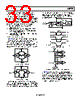
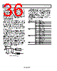
36 / 50 page  AD9739 Data Sheet Rev. E | Page 36 of 50 If lock is lost, the mu controller has the option of remaining in the tracking loop or resetting and starting the search again via the CONTRST bit (Register 0x29, Bit 5). Continued tracking is the preferred state because it is the least disruptive to a system in which the AD9739 temporarily loses lock. The user can poll the mu delay and phase value by first setting the read bit high (Register 0x26, Bit 3). Once the read bit is set, the MUDEL[8:0] bits and the SET_PHS[4:0] bits (Register 0x27 and Register 0x28) that the controller is currently using can be read. INTERRUPT REQUESTS The AD9739 can provide the host processor with an interrupt request output signal (IRQ) that indicates that one or more of the AD9739 internal controllers have achieved lock or lost lock. These controllers include the mu, data receiver, and synchronization controllers. The host can then poll the IRQ status register (Register 0x04) to determine which controller has lost lock. The IRQ output signal is an active high output signal available on Pin F13. If used, its output should be connected via a 10 kΩ pull-up resistor to VDD33. Each IRQ is enabled by setting the enable bits in Register 0x03, which purposely has the same bit mapping as the IRQ status bits in Register 0x04. Note that these IRQ status bits are set only when the controller transitions from a false to true state. Therefore, it is possible for the x_LCK_IRQ and x_LST_IRQ status bits to be set when a controller temporarily loses lock but is able to reestablish lock before the IRQ is serviced by the host. In this case, the host should validate the present status of the suspect controller by reading back its current status bits, which are available in Register 0x21 and/or Register 0x2A. Based on the status of these bits, the host can take appropriate action, if required, to reestablish lock. To clear an IRQ after servicing, it is necessary to reset relevant bits in Register 0x03 by writing 0 followed by another write of 1 to reenable. A detailed diagram of the interrupt circuitry is shown in Figure 51. INT(n) Q D INT SOURCE SPI ISR READ DATA (PIN F13) SPI WRITE INT SOURCE SPI ADDRESS DATA = 1 IMR SCLK SPI DATA Figure 51. Interrupt Request Circuitry It is also possible to use the IRQ during the AD9739 initialization phase after power-up to determine when the mu and data receiver controllers have achieved lock. For example, before enabling the mu controller, the MU_LCK_EN bit (Register 0x03, Bit 2) can be set and the IRQ output signal monitored to determine when lock has been established before continuing in a similar manner with the data receiver controllers. Note that the relevant LCK bit should be cleared before continuing to the next controller. After all controllers are locked, the lost lock enable bits (that is, x_LST_EN) should be set. Table 29. Interrupt Request Registers Address (Hex) Bit Description 0x03 5 SYNC_LST_EN 4 SYNC_LCK_EN 3 MU_LST_EN 2 MU_LCK_EN 1 RCV_LST_EN 0 RCV_LCK_EN 0x04 5 SYNC_LST_IRQ 4 SYNC_LCK_IRQ 3 MU_LST_IRQ 2 MU_LCK_IRQ 1 RCV_LST_IRQ 0 RCV_LCK_IRQ 0x21 7 SYNC_TRK_ON 5 SYNC_LST 4 SYNC_LCK 3 RCVR_TRK_ON 1 RCVR_LST 0 RCVR_LCK 0x2A 1 MU_LST 0 MU_LKD |
|
链接网址 |
| ALLDATASHEET是否为您带来帮助? [ DONATE ] |
关于 Alldatasheet | 广告服务 | 联系我们 | 隐私政策 | 数据表链接 | 链接交换 | 制造商名单 All Rights Reserved©Alldatasheet.com |
| Russian : Alldatasheetru.com | Korean : Alldatasheet.co.kr | Spanish : Alldatasheet.es | French : Alldatasheet.fr | Italian : Alldatasheetit.com Portuguese : Alldatasheetpt.com | Polish : Alldatasheet.pl | Vietnamese : Alldatasheet.vn Indian : Alldatasheet.in | Mexican : Alldatasheet.com.mx | British : Alldatasheet.co.uk | New Zealand : Alldatasheet.co.nz |
|
Family Site : ic2ic.com |
icmetro.com |
 Chinese ▼
 English
 Chinese
 German
 Japanese
 Russian
 Korean
 Spanish
 French
 Italian
 Portuguese
 Polish
 Vietnamese
 Indian
 Mexican
 British
 New Zealand