|
数据搜索系统,热门电子元器件搜索 |
|
|
数据搜索系统,热门电子元器件搜索 |
|
AD9739-R2-EBZ 数据表(PDF) 42 Page - Analog Devices |
|
|
|||||||||||||||||||||||||||||
AD9739-R2-EBZ 数据表(HTML) 42 Page - Analog Devices |
|
|
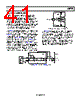
42 / 50 page  AD9739 Data Sheet Rev. E | Page 42 of 50 0.70 0.75 0.80 0.85 0.90 0.95 1.00 1.05 1.10 –15 –13 –11 –9 –7 –5 –3 –1 1 3 5 7 9 11 13 15 OFFSET CODE CLKP CLKN Figure 60. Common-Mode Voltage with Respect to CLKP_OFFSET/CLKN_OFFSET and DIR_P/DIR_N VOLTAGE REFERENCE The AD9739 output current is set by a combination of digital control bits and the I120 reference current, as shown in Figure 61. CURRENT SCALING FSC[9:0] AD9739 DAC IFULL-SCALE 10kΩ 1nF VREF I120 AGND I120 VBG 1.2V + – Figure 61. Voltage Reference Circuit The reference current is obtained by forcing the band gap voltage across an external 10 kΩ resistor from I120 (Pin B14) to ground. The 1.2 V nominal band gap voltage (VREF) generates a 120 µA reference current in the 10 kΩ resistor. Note the following constraints when configuring the voltage reference circuit: • Both the 10 kΩ resistor and 1 nF bypass capacitor are required for proper operation. • Adjusting the output full-scale current, I OUTFS, of the DAC from its default setting of 20 mA should be performed digitally. • The AD9739 is not a multiplying DAC. Modulating the reference current, I120, with an ac signal is not supported. • The band gap voltage appearing at VREF (Pin C14) must be buffered for use with external circuitry because its output impedance is approximately 5 kΩ. • An external reference can be used to overdrive the internal reference by connecting it to VREF (Pin C14). I OUTFS can be adjusted digitally over 8.7 mA to 31.7 mA by using FSC[9:0] (Register 0x06 and Register 0x07). The following equation relates I OUTFS to the FSC[9:0] register, which can be set from 0 to 1023: I OUTFS = 22.6 × FSC[9:0]/1000 + 8.7 (1) Note that a default value of 0x200 generates 20 mA full scale, which is used for most of the characterization presented in this data sheet (unless noted otherwise). ANALOG OUTPUTS Equivalent DAC Output and Transfer Function The AD9739 provides complementary current outputs, IOUTP and IOUTN, that source current into an external ground reference load. Figure 62 shows an equivalent output circuit for the DAC. Note that, compared to most current output DACs of this type, the AD9739 outputs exhibit a slight offset current (that is, I OUTFS/16), and the peak differential ac current is slightly below I OUTFS/2 (that is, 15/32 × IOUTFS). 17/32 × IOUTFS IPEAK = 15/32 × IOUTFS AC 70Ω 2.2pF IOUTFS = 8.6 – 31.2mA 17/32 × IOUTFS Figure 62. Equivalent DAC Output Circuit As shown in Figure 62, the DAC output can be modeled as a pair of dc current sources that source a current of 17/32 × I OUTFS to each output. A differential ac current source, I PEAK, is used to model the signal-dependent nature of the DAC output. The polarity and signal dependency of this ac current source are related to the digital code by the following equations: F(Code) = (DACCODE − 8192)/8192 (2) −1 ≤ F(Code) < 1 (3) where DACCODE = 0 to 16,383 (decimal). Because I PEAK can swing ±(15/32) × IOUTFS, the output currents measured at IOUTP and IOUTN can span from I OUTFS/16 to I OUTFS. However, because the ac signal-dependent current component is complementary, the sum of the two outputs is always constant (that is, IOUTP + IOUTN = (34/32) × I OUTFS). The code-dependent current measured at the IOUTP (and IOUTN) output is as follows: IOUTP = 17/32 × I OUTFS + 15/32 × IOUTFS × F(Code) (4) IOUTN = 17/32 × I OUTFS − 15/32 × IOUTFS × F(Code) (5) |
|
链接网址 |
| ALLDATASHEET是否为您带来帮助? [ DONATE ] |
关于 Alldatasheet | 广告服务 | 联系我们 | 隐私政策 | 数据表链接 | 链接交换 | 制造商名单 All Rights Reserved©Alldatasheet.com |
| Russian : Alldatasheetru.com | Korean : Alldatasheet.co.kr | Spanish : Alldatasheet.es | French : Alldatasheet.fr | Italian : Alldatasheetit.com Portuguese : Alldatasheetpt.com | Polish : Alldatasheet.pl | Vietnamese : Alldatasheet.vn Indian : Alldatasheet.in | Mexican : Alldatasheet.com.mx | British : Alldatasheet.co.uk | New Zealand : Alldatasheet.co.nz |
|
Family Site : ic2ic.com |
icmetro.com |
 Chinese ▼
 English
 Chinese
 German
 Japanese
 Russian
 Korean
 Spanish
 French
 Italian
 Portuguese
 Polish
 Vietnamese
 Indian
 Mexican
 British
 New Zealand