|
数据搜索系统,热门电子元器件搜索 |
|
|
数据搜索系统,热门电子元器件搜索 |
|
EM357-RTR 数据表(PDF) 176 Page - List of Unclassifed Manufacturers |
|
|
|||||||||||||||||||||||||||||
EM357-RTR 数据表(HTML) 176 Page - List of Unclassifed Manufacturers |
|
|
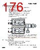
176 / 240 page  EM351 / EM357 10 ADC (Analog to Digital Converter) The EM35x ADC is a first-order sigma-delta converter with the following features: Resolution of up to 14 bits Sample times as fast as 5.33 µs (188 kHz) Differential and single-ended conversions from six external and four internal sources Two voltage ranges (differential): -VREF to +VREF, and –VDD_PADS to +VDD_PADS Choice of internal or external VREF internal VREF may be output to PB0 or external VREF may be derived from PB0 Digital offset and gain correction Dedicated DMA channel with one-shot and continuous operating modes Figure 10-1 shows the basic ADC structure. Figure 10-1. ADC Block Diagram While the ADC Module supports both single-ended and differential inputs, the ADC input stage always operates in differential mode. Single-ended conversions are performed by connecting one of the differential inputs to VREF/2 while fully differential operation uses two external inputs. Note: The regulator input voltage, VDD_PADS, cannot be measured using the ADC, but it can be measured through Ember software. 10.1 Setup and Configuration To use the ADC follow this procedure, described in more detail in the next sections: Configure any GPIO pins to be used by the ADC in analog mode. Configure the voltage reference (internal or external). Set the offset and gain values. If using DMA, reset the ADC DMA, define the DMA buffer, and start the DMA in the proper transfer mode. 10-1 120-035X-000D Preliminary |
|
链接网址 |
| ALLDATASHEET是否为您带来帮助? [ DONATE ] |
关于 Alldatasheet | 广告服务 | 联系我们 | 隐私政策 | 数据表链接 | 链接交换 | 制造商名单 All Rights Reserved©Alldatasheet.com |
| Russian : Alldatasheetru.com | Korean : Alldatasheet.co.kr | Spanish : Alldatasheet.es | French : Alldatasheet.fr | Italian : Alldatasheetit.com Portuguese : Alldatasheetpt.com | Polish : Alldatasheet.pl | Vietnamese : Alldatasheet.vn Indian : Alldatasheet.in | Mexican : Alldatasheet.com.mx | British : Alldatasheet.co.uk | New Zealand : Alldatasheet.co.nz |
|
Family Site : ic2ic.com |
icmetro.com |
 Chinese ▼
 English
 Chinese
 German
 Japanese
 Russian
 Korean
 Spanish
 French
 Italian
 Portuguese
 Polish
 Vietnamese
 Indian
 Mexican
 British
 New Zealand