|
数据搜索系统,热门电子元器件搜索 |
|
|
数据搜索系统,热门电子元器件搜索 |
|
EM357-RTR 数据表(PDF) 137 Page - List of Unclassifed Manufacturers |
|
|
|||||||||||||||||||||||||||||
EM357-RTR 数据表(HTML) 137 Page - List of Unclassifed Manufacturers |
|
|
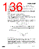
137 / 240 page  EM351 / EM357 Because the buffer registers are only transferred to the shadow registers when a UEV occurs, before starting the counter initialize all the registers by setting the TIM_UG bit in the TIMx_EGR register. OCy polarity is software programmable using the TIM_CCyP bit in the TIMx_CCER register. It can be programmed as active high or active low. OCy output is enabled by the TIM_CCyE bit in the TIMx_CCER register. Refer to the TIMx_CCER register description in the Registers section for more details. In PWM mode (1 or 2), TIMx_CNT and TIMx_CCRy are always compared to determine whether TIMx_CCRy ≤ TIMx_CNT or TIMx_CNT ≤ TIMx_CCRy,depending on the direction of the counter. The OCyREF signal is asserted only: When the result of the comparison changes, or When the output compare mode (TIM_OCyM bits in the TIMx_CCMR1 register) switches from the “frozen” configuration (no comparison, TIM_OCyM = 000) to one of the PWM modes (TIM_OCyM = 110 or 111). This allows software to force a PWM output to a particular state while the timer is running. The timer is able to generate PWM in edge-aligned mode or center-aligned mode depending on the TIM_CMS bits in the TIMx_CR1 register. 9.3.9.1 PWM Edge-Aligned Mode: Up-Counting Configuration Up-counting is active when the TIM_DIR bit in the TIMx_CR1 register is low. Refer to the section Up-Counting Mode. The following example uses PWM mode 1. The reference PWM signal OCyREF is high as long as TIMx_CNT < TIMx_CCRy, otherwise it becomes low. If the compare value in TIMx_CCRy is greater than the auto-reload value in TIMx_ARR, then OCyREF is held at 1. If the compare value is 0, then OCyREF is held at 0. Figure 9-22 shows some edge-aligned PWM waveforms in an example, where TIMx_ARR = 8. Figure 9-22. Edge-Aligned PWM Waveforms (ARR = 8) 9.3.9.2 PWM Edge-Aligned Mode: Down-Counting Configuration Down-counting is active when the TIM_DIR bit in the TIMx_CR1 register is high. Refer to the Down-Counting Mode section for more information. In PWM mode 1, the reference signal OCyREF is low as long as TIMx_CNT > TIMx_CCRy, otherwise it becomes high. If the compare value in TIMx_CCRy is greater than the auto-reload value in TIMx_ARR, then OCyREF is held at 1. Zero-percent PWM is not possible in this mode. 9-17 120-035X-000D Preliminary |
|
链接网址 |
| ALLDATASHEET是否为您带来帮助? [ DONATE ] |
关于 Alldatasheet | 广告服务 | 联系我们 | 隐私政策 | 数据表链接 | 链接交换 | 制造商名单 All Rights Reserved©Alldatasheet.com |
| Russian : Alldatasheetru.com | Korean : Alldatasheet.co.kr | Spanish : Alldatasheet.es | French : Alldatasheet.fr | Italian : Alldatasheetit.com Portuguese : Alldatasheetpt.com | Polish : Alldatasheet.pl | Vietnamese : Alldatasheet.vn Indian : Alldatasheet.in | Mexican : Alldatasheet.com.mx | British : Alldatasheet.co.uk | New Zealand : Alldatasheet.co.nz |
|
Family Site : ic2ic.com |
icmetro.com |
 Chinese ▼
 English
 Chinese
 German
 Japanese
 Russian
 Korean
 Spanish
 French
 Italian
 Portuguese
 Polish
 Vietnamese
 Indian
 Mexican
 British
 New Zealand