|
数据搜索系统,热门电子元器件搜索 |
|
|
数据搜索系统,热门电子元器件搜索 |
|
XIO2000 数据表(PDF) 22 Page - Texas Instruments |
|
|
|||||||||||||||||||||||||||||
XIO2000 数据表(HTML) 22 Page - Texas Instruments |
|
|
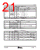
22 / 150 page  Introduction 10 November 2005 SCPS097B Table 2−6. PCI Express Terminals SIGNAL BALL I/O TYPE CELL TYPE CLAMP RAIL EXTERNAL PARTS DESCRIPTION PERST J17 I LV CMOS VDD_33_ COMBIO − PCI Express reset input. The PERST signal identifies when the system power is stable and generates an internal power on reset. Note: The PERST input buffer has hysteresis. REF0_PCIE REF1_PCIE L16 L17 I/O BIAS − External resistor External reference resistor + and − terminals for setting TX driver current. An external resistor is connected between terminals L16 and L17. RXP RXN E17 E16 DI HS DIFF IN VSS − High-speed receive pair. RXP and RXN comprise the differential receive pair for the single PCI Express lane supported. TXP TXN H17 H16 DO HS DIFF OUT VDD_15 Series capacitors High-speed transmit pair. TXP and TXN comprise the differential transmit pair for the single PCI Express lane supported. WAKE M16 O LV CMOS VDD_33_ COMBIO − Wake is an active low signal that is driven low to reactivate the PCI Express link hierarchy’s main power rails and reference clocks. Note: Since WAKE is an open-drain output buffer, a system side pullup resistor is required. Table 2−7. Clock Terminals SIGNAL BALL I/O TYPE CELL TYPE CLAMP RAIL EXTERNAL PARTS DESCRIPTION REFCLK_SEL A16 I LV CMOS VDD_33 Pullup or pulldown resistor Reference clock select. This terminal selects the reference clock input. 0 = 100-MHz differential common reference clock used. 1 = 125-MHz single-ended, reference clock used. REFCLK+ C17 DI HS DIFF IN VDD_33 − Reference clock. REFCLK+ and REFCLK− comprise the differential input pair for the 100-MHz system reference clock. For a single-ended, 125-MHz system reference clock, use the REFCLK+ input. REFCLK− C16 DI HS DIFF IN VDD_33 Capacitor to VSS for single-ended mode Reference clock. REFCLK+ and REFCLK− comprise the differential input pair for the 100-MHz system reference clock. For a single-ended, 125-MHz system reference clock, attach a capacitor from REFCLK− to VSS. CLK P03 I PCI Bus VCCP − PCI clock input. This is the clock input to the PCI bus core. CLKOUT0 CLKOUT1 CLKOUT2 CLKOUT3 CLKOUT4 CLKOUT5 CLKOUT6 C08 B09 B10 A11 A12 A13 B14 O PCI Bus VCCP − PCI clock outputs. These clock outputs are used to clock the PCI bus. If the bridge PCI bus clock outputs are used, then CLKOUT6 must be connected to the CLK input. |
|
链接网址 |
| ALLDATASHEET是否为您带来帮助? [ DONATE ] |
关于 Alldatasheet | 广告服务 | 联系我们 | 隐私政策 | 数据表链接 | 链接交换 | 制造商名单 All Rights Reserved©Alldatasheet.com |
| Russian : Alldatasheetru.com | Korean : Alldatasheet.co.kr | Spanish : Alldatasheet.es | French : Alldatasheet.fr | Italian : Alldatasheetit.com Portuguese : Alldatasheetpt.com | Polish : Alldatasheet.pl | Vietnamese : Alldatasheet.vn Indian : Alldatasheet.in | Mexican : Alldatasheet.com.mx | British : Alldatasheet.co.uk | New Zealand : Alldatasheet.co.nz |
|
Family Site : ic2ic.com |
icmetro.com |
 Chinese ▼
 English
 Chinese
 German
 Japanese
 Russian
 Korean
 Spanish
 French
 Italian
 Portuguese
 Polish
 Vietnamese
 Indian
 Mexican
 British
 New Zealand