|
数据搜索系统,热门电子元器件搜索 |
|
|
数据搜索系统,热门电子元器件搜索 |
|
ADP1046ACPZ-R7 数据表(PDF) 19 Page - Analog Devices |
|
|
|||||||||||||||||||||||||||||
ADP1046ACPZ-R7 数据表(HTML) 19 Page - Analog Devices |
|
|
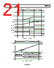
19 / 96 page  Data Sheet ADP1046 Rev. 0 | Page 19 of 96 SYNCHRONOUS RECTIFICATION SR1 and SR2 are recommended for use as the PWM control signals when using synchronous rectification. These PWM signals can be configured much like the other PWM outputs. An optional soft start can be applied to the synchronous rectifier PWM outputs. The SR soft start can be programmed using Register 0x54[1:0]. When SR soft start is disabled (Register 0x54[0] = 0), the SR signals are turned on to their full PWM duty cycle values immediately. When SR soft start is enabled (Register 0x54[0] = 1), the SR signals ramp up from zero duty cycle to the desired duty cycle in steps of 40 ns per switching cycle. The advantage of ramping the SR signals is to minimize the output voltage step that occurs when the SR FETs are turned on without a soft start. The advantage of turning the SR signals completely on immediately is that they can help to minimize the voltage transient caused by a load step. Using Register 0x54[1], the SR soft start can be programmed to occur only once (the first time that the SR signals are enabled) or every time that the SR signals are enabled, for example, when the system enters or exits light load mode. When programming the ADP1046 to use SR soft start, ensure correct operation of this function by setting the falling edge of SR1 (t10) to a lower value than the rising edge of SR1 (t9) and by setting the falling edge of SR2 (t12) to a lower value than the rising edge of SR2 (t11). SR soft start can also be disabled by setting Register 0x0F[7] = 1. SR (SYNCHRONOUS RECTIFIER) DELAY The ADP1046 is well suited for dc-to-dc converters in isolated topologies. Every time a PWM signal crosses the isolation barrier an additional propagation delay is added due to the isolating components. The ADP1046 allows programming of an adjustable delay (0 ns to 315 ns in steps of 5 ns) using Register 0x79[5:0]. This delay moves both SR1 and SR2 later in time to compensate for the added delay due to the isolating components (see Figure 56). In this way, the edges of all PWM outputs can be aligned, and the SR delay can be applied separately as a constant dead time. ADAPTIVE DEAD TIME CONTROL A set of registers called the adaptive dead time (ADT) registers (Register 0x68 to Register 0x70) allows the dead time between PWM edges to be adapted on the fly. The ADP1046 uses the ADT only when the modulation is below the dead time (primary current) threshold programmed in Register 0x68. The Analog Devices software GUI allows the user to easily program the dead time values, and it is recommended that the GUI be used for this purpose. Before ADT is configured, the primary current threshold must be programmed. Each individual PWM rising and falling edge (t1 to t14) can then be programmed to have a specific dead time offset at no load (zero current). This offset can be positive or negative and is relative to the nominal edge position. When the CS1 current is between zero and the current threshold, the amount of dead time is linearly adjusted in steps of 5 ns. The averaging period of the CS1 current and the speed of the dead time adjustment can also be programmed in Register 0x70 to accommodate faster or slower adjustment. For example, if the CS1 threshold is set to 2 A, t1 has a nominal rising edge of 100 ns. If the ADT setting for t1 is 40 ns at no load, t1 moves to 140 ns when the current is 0 A and to 120 ns when the current is 1 A. Similarly, ADT can be applied in the negative direction. LIGHT LOAD MODE The ADP1046 can be configured to disable PWM outputs under light load conditions based on the value of CS2. Register 0x3B and Register 0x7D are used to program the light load mode thresholds for turn-off and turn-on of SR1, SR2, and other PWM outputs. Below the light load threshold programmed in Register 0x3B, the SR outputs are disabled; the user can also program any of the other PWM outputs to shut down below this threshold. Light load mode allows the ADP1046 to be used with interleaved topologies that incorporate automatic phase shedding at light load. To prevent the system from oscillating between light load and normal modes due to the thresholds being programmed too close to each other, a programmable debounce is provided in Register 0x7D[5:4]. This debounce prevents the part from changing state within the programmed interval. The speed of the SR enable is programmable from 37.5 μs to 300 μs in four discrete steps using Register 0x7D[3:2]. This ensures that, in case of a load step, the SR signals (and any other PWM outputs that are temporarily disabled) can be turned on quickly enough to prevent damage to the FETs that they are controlling. The light load mode digital filter is also used during light load mode. MODULATION LIMIT The modulation limit register (Register 0x2E) can be programmed to apply a maximum duty cycle modulation limit to any PWM signal, thus limiting the modulation range of any PWM output. When modulation is enabled, the maximum modulation limit is applied to all PWM outputs collectively. As shown in Figure 21, this limit is the maximum time variation for the modulated edges from the default timing, following the configured modulation direction. There is no minimum duty cycle limit setting. Therefore, the user must set the rising edges and falling edges based on the case with the least modulation. OUTx tMODULATION_LIMIT tRX tFX Figure 21. Modulation Limit Settings |
|
链接网址 |
| ALLDATASHEET是否为您带来帮助? [ DONATE ] |
关于 Alldatasheet | 广告服务 | 联系我们 | 隐私政策 | 数据表链接 | 链接交换 | 制造商名单 All Rights Reserved©Alldatasheet.com |
| Russian : Alldatasheetru.com | Korean : Alldatasheet.co.kr | Spanish : Alldatasheet.es | French : Alldatasheet.fr | Italian : Alldatasheetit.com Portuguese : Alldatasheetpt.com | Polish : Alldatasheet.pl | Vietnamese : Alldatasheet.vn Indian : Alldatasheet.in | Mexican : Alldatasheet.com.mx | British : Alldatasheet.co.uk | New Zealand : Alldatasheet.co.nz |
|
Family Site : ic2ic.com |
icmetro.com |
 Chinese ▼
 English
 Chinese
 German
 Japanese
 Russian
 Korean
 Spanish
 French
 Italian
 Portuguese
 Polish
 Vietnamese
 Indian
 Mexican
 British
 New Zealand