|
数据搜索系统,热门电子元器件搜索 |
|
|
数据搜索系统,热门电子元器件搜索 |
|
EM357-RTR 数据表(PDF) 95 Page - Silicon Laboratories |
|
|
|||||||||||||||||||||||||||||
EM357-RTR 数据表(HTML) 95 Page - Silicon Laboratories |
|
|
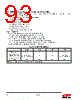
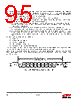
95 / 241 page  95 Rev 1.3 For example, if the baud rate tolerance between receive and transmit is 200 ppm (reasonable if both sides are derived from a crystal), and the baud rate is 115200 bps, then errors will not occur until the inter-byte gap exceeds 43 ms. If the gap is exceeded then the chance of an error is essentially random, with a probability of approximately P = baud / 24e6. At 115200 bps, the probability of corruption is 0.5%. The UART character frame format is determined by four bits in the SC1_UARTCFG register: SC_UART8BIT specifies the number of data bits in received and transmitted characters. If this bit is clear, characters have 7 data bits; if set, characters have 8 data bits. SC_UART2STP selects the number of stop bits in transmitted characters. (Only one stop bit is required in received characters.) If this bit is clear, characters are transmitted with one stop bit; if set, characters are transmitted with two stop bits. SC_UARTPAR controls whether or not received and transmitted characters include a parity bit. If SC_UARTPAR is clear, characters do not contain a parity bit, otherwise, characters do contain a parity bit. SC_UARTODD specifies whether transmitted and received parity bits contain odd or even parity. If this bit is clear, the parity bit is even, and if set, the parity bit is odd. Even parity is the exclusive-or of all of the data bits, and odd parity is the inverse of the even parity value. SC_UARTODD has no effect if SC_UARTPAR is clear. A UART character frame contains, in sequence: The start bit The least significant data bit The remaining data bits If parity is enabled, the parity bit The stop bit, or bits, if 2 stop bits are selected. Figure 8.3 shows the UART character frame format, with optional bits indicated. Depending on the options chosen for the character frame, the length of a character frame ranges from 9 to 12 bit times. Note that asynchronous serial data may have arbitrarily long idle periods between characters. When idle, serial data (TXD or RXD) is held in the high state. Serial data transitions to the low state in the start bit at the beginning of a character frame. Figure 8.3. UART Character Frame Format Idle time Start Bit Data Bit 0 Data Bit 1 Data Bit 2 Data Bit 3 Data Bit 4 Data Bit 5 Data Bit 6 Data Bit 7 Parity Bit Stop Bit Stop Bit Next Start Bit or IdleTime UART Character Frame Format (optional sections are in italics) TXD or RXD |
|
链接网址 |
| ALLDATASHEET是否为您带来帮助? [ DONATE ] |
关于 Alldatasheet | 广告服务 | 联系我们 | 隐私政策 | 数据表链接 | 链接交换 | 制造商名单 All Rights Reserved©Alldatasheet.com |
| Russian : Alldatasheetru.com | Korean : Alldatasheet.co.kr | Spanish : Alldatasheet.es | French : Alldatasheet.fr | Italian : Alldatasheetit.com Portuguese : Alldatasheetpt.com | Polish : Alldatasheet.pl | Vietnamese : Alldatasheet.vn Indian : Alldatasheet.in | Mexican : Alldatasheet.com.mx | British : Alldatasheet.co.uk | New Zealand : Alldatasheet.co.nz |
|
Family Site : ic2ic.com |
icmetro.com |
 Chinese ▼
 English
 Chinese
 German
 Japanese
 Russian
 Korean
 Spanish
 French
 Italian
 Portuguese
 Polish
 Vietnamese
 Indian
 Mexican
 British
 New Zealand