|
数据搜索系统,热门电子元器件搜索 |
|
|
数据搜索系统,热门电子元器件搜索 |
|
EM357-RTR 数据表(PDF) 97 Page - Silicon Laboratories |
|
|
|||||||||||||||||||||||||||||
EM357-RTR 数据表(HTML) 97 Page - Silicon Laboratories |
|
|
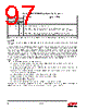
97 / 241 page  97 Rev 1.3 8.6.5. DMA "8.7. DMA Channels" on page 101 describes how to configure and use the serial receive and transmit DMA channels. The receive DMA channel has special provisions to record UART receive errors. When the DMA channel transfers a character from the receive FIFO to a buffer in memory, it checks the stored parity and frame error status flags. When an error is flagged, the SC1_RXERRA/B register is updated, marking the offset to the first received character with a parity or frame error. Similarly if a receive overrun error occurs, the SC1_RXERRA/B registers mark the error offset. The receive FIFO hardware generates the INT_SCRXOVF interrupt and DMA status register indicates the error immediately, but in this case the error offset is 4 characters ahead of the actual overflow at the input to the receive FIFO. Two conditions will clear the error indication: setting the appropriate SC_RXDMARST bit in the SC1_DMACTRL register, or loading the appropriate DMA buffer after it has unloaded. 8.6.6. Interrupts UART interrupts are generated on the following events: Transmit FIFO empty and last character shifted out (depending on SCx_INTMODE, either the 0 to 1 transition or the high level of SC_UARTTXIDLE) Transmit FIFO changed from full to not full (depending on SCx_INTMODE, either the 0 to 1 transition or the high level of SC_UARTTXFREE) Receive FIFO changed from empty to not empty (depending on SCx_INTMODE, either the 0 to 1 transition or the high level of SC_UARTRXVAL) Transmit DMA buffer A/B complete (1 to 0 transition of SC_TXACTA/B) Receive DMA buffer A/B complete (1 to 0 transition of SC_RXACTA/B) Character received with parity error Character received with frame error Character received and lost when receive FIFO was full (receive overrun error) To enable CPU interrupts, set the desired interrupt bits in the second-level INT_SCxCFG register, and enable the top-level SCx interrupt in the NVIC by writing the INT_SCx bit in the INT_CFGSET register. Table 8.12. UART RTS/CTS Flow Control Configurations SC1_UARTCFG Pins Used Operating Mode SC_UARTxxx* FLOW AUTO RTS 0 — — TXD, RXD No RTS/CTS flow control 1 0 0/1 TXD, RXD, nCTS, nRTS Flow control using RTS/CTS with software control of nRTS: nRTS controlled by SC_UARTRTS bit in SC1_UARTCFG register 1 1 — TXD, RXD, nCTS, nRTS Flow control using RTS/CTS with hardware control of nRTS: nRTS is asserted if room for at least 2 characters in receive FIFO *Note: The notation “xxx” means that the corresponding column header below is inserted to form the field name. |
|
链接网址 |
| ALLDATASHEET是否为您带来帮助? [ DONATE ] |
关于 Alldatasheet | 广告服务 | 联系我们 | 隐私政策 | 数据表链接 | 链接交换 | 制造商名单 All Rights Reserved©Alldatasheet.com |
| Russian : Alldatasheetru.com | Korean : Alldatasheet.co.kr | Spanish : Alldatasheet.es | French : Alldatasheet.fr | Italian : Alldatasheetit.com Portuguese : Alldatasheetpt.com | Polish : Alldatasheet.pl | Vietnamese : Alldatasheet.vn Indian : Alldatasheet.in | Mexican : Alldatasheet.com.mx | British : Alldatasheet.co.uk | New Zealand : Alldatasheet.co.nz |
|
Family Site : ic2ic.com |
icmetro.com |
 Chinese ▼
 English
 Chinese
 German
 Japanese
 Russian
 Korean
 Spanish
 French
 Italian
 Portuguese
 Polish
 Vietnamese
 Indian
 Mexican
 British
 New Zealand