|
数据搜索系统,热门电子元器件搜索 |
|
|
数据搜索系统,热门电子元器件搜索 |
|
EM357-RTR 数据表(PDF) 101 Page - Silicon Laboratories |
|
|
|||||||||||||||||||||||||||||
EM357-RTR 数据表(HTML) 101 Page - Silicon Laboratories |
|
|
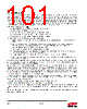
101 / 241 page  101 Rev 1.3 8.7. DMA Channels The EM35x serial DMA channels enable efficient, high-speed operation of the SPI and UART controllers by reducing the load on the CPU as well as decreasing the frequency of interrupts that it must service. The transmit and receive DMA channels can transfer data between the transmit and receive FIFOs and the DMA buffers in main memory as quickly as it can be transmitted or received. Once software defines, configures, and activates the DMA, it only needs to handle an interrupt when a transmit buffer has been emptied or a receive buffer has been filled. The DMA channels each support two memory buffers, labeled A and B, and can alternate ("ping-pong") between them automatically to allow continuous communication without critical interrupt timing. Note: DMA memory buffer terminology load - make a buffer available for the DMA channel to use pending - a buffer loaded but not yet active active - the buffer that will be used for the next DMA transfer unload - DMA channel action when it has finished with a buffer idle - a buffer that has not been loaded, or has been unloaded To use a DMA channel, software should follow these steps: 1. Reset the DMA channel by setting the SC_TXDMARST (or SC_RXDMARST) bit in the SCx_DMACTRL register. 2. Set up the DMA buffers. The two DMA buffers, A and B, are defined by writing the start address to SCx_TXBEGA/B (or SCx_RXBEGA/B) and the (inclusive) end address to SCx_TXENDA/B (or SCx_RXENDA/B). Note that DMA buffers must be in RAM. 3. Configure and initialize SCx for the desired operating mode. 4. Enable second-level interrupts triggered when DMA buffers unload by setting the INT_SCTXULDA/B (or INT_SCRXULDA/B) bits in the INT_SCxFLAG register. 5. Enable top-level NVIC interrupts by setting the INT_SCx bit in the INT_CFGSET register. 6. Start the DMA by loading the DMA buffers by setting the SC_TXLODA/B (or SC_RXLODA/B) bits in the SCx_DMACTRL register. A DMA buffer's end address, SCx_TXENDA/B (or SCx_RXENDA/B), can be written while the buffer is loaded or active. This is useful for receiving messages that contain an initial byte count, since it allows software to set the buffer end address at the last byte of the message. As the DMA channel transfers data between the transmit or receive FIFO and a memory buffer, the DMA count register contains the byte offset from the start of the buffer to the address of the next byte that will be written or read. A transmit DMA channel has a single DMA count register (SCx_TXCNT) that applies to whichever transmit buffer is active, but a receive DMA channel has two DMA count registers (SCx_RXCNTA/B), one for each receive buffer. The DMA count register contents are preserved until the corresponding buffer, or either buffer in the case of the transmit DMA count, is loaded, or until the DMA is reset. The receive DMA count register may be written while the corresponding buffer is loaded. If the buffer is not loaded, writing the DMA count register also loads the buffer while preserving the count value written. This feature can simplify handling UART receive errors. The DMA channel stops using a buffer and unloads it when the following is true: (DMA buffer start address + DMA buffer count) > DMA buffer end address Typically a transmit buffer is unloaded after all its data has been sent, and a receive buffer is unloaded after it is filled with data, but writing to the buffer end address or buffer count registers can also cause a buffer to unload early. Serial controller DMA channels include additional features specific to the SPI and UART operation and are described in those sections. |
|
链接网址 |
| ALLDATASHEET是否为您带来帮助? [ DONATE ] |
关于 Alldatasheet | 广告服务 | 联系我们 | 隐私政策 | 数据表链接 | 链接交换 | 制造商名单 All Rights Reserved©Alldatasheet.com |
| Russian : Alldatasheetru.com | Korean : Alldatasheet.co.kr | Spanish : Alldatasheet.es | French : Alldatasheet.fr | Italian : Alldatasheetit.com Portuguese : Alldatasheetpt.com | Polish : Alldatasheet.pl | Vietnamese : Alldatasheet.vn Indian : Alldatasheet.in | Mexican : Alldatasheet.com.mx | British : Alldatasheet.co.uk | New Zealand : Alldatasheet.co.nz |
|
Family Site : ic2ic.com |
icmetro.com |
 Chinese ▼
 English
 Chinese
 German
 Japanese
 Russian
 Korean
 Spanish
 French
 Italian
 Portuguese
 Polish
 Vietnamese
 Indian
 Mexican
 British
 New Zealand