|
数据搜索系统,热门电子元器件搜索 |
|
|
数据搜索系统,热门电子元器件搜索 |
|
EM357-RTR 数据表(PDF) 42 Page - Silicon Laboratories |
|
|
|||||||||||||||||||||||||||||
EM357-RTR 数据表(HTML) 42 Page - Silicon Laboratories |
|
|
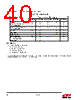
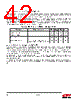
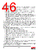
42 / 241 page  42 Rev 1.3 6.3.1. High-Frequency Internal RC Oscillator (OSCHF) The high-frequency RC oscillator (OSCHF) is used as the default system clock source when power is applied to the core domain. The nominal frequency coming out of reset is 12 MHz and Ember software calibrates this clock to 12 MHz. Table 6.6 contains the specification for the high frequency RC oscillator. Most peripherals, excluding the radio peripheral, are fully functional using the OSCHF clock source. Application software must be aware that peripherals are clocked at different speeds depending on whether OSCHF or OSC24M is being used. Since the frequency step of OSCHF is 0.3 MHz and the high-frequency crystal oscillator is used for calibration, the calibrated accuracy of OSCHF is ±150 kHz ±40 ppm. The UART and ADC peripherals may not be usable due to the lower accuracy of the OSCHF frequency. 6.3.2. High-Frequency Crystal Oscillator (OSC24M) The high-frequency crystal oscillator (OSC24M) requires an external 24 MHz crystal with an accuracy of ±40 ppm. Based upon the application’s bill of materials and current consumption requirements, the external crystal may cover a range of ESR requirements. Table 6.7 contains the specification for the high frequency crystal oscillator. The crystal oscillator has a software-programmable bias circuit to minimize current consumption. Ember software configures the bias circuit for minimum current consumption. All peripherals including the radio peripheral are fully functional using the OSC24M clock source. Application software must be aware that peripherals are clocked at different speeds depending on whether OSCHF or OSC24M is being used. If the 24 MHz crystal fails, a hardware failover mechanism forces the system to switch back to the high-frequency RC oscillator as the main clock source, and a non-maskable interrupt (NMI) is signaled to the ARM® CortexTM-M3 NVIC. Table 6.6. High-Frequency RC Oscillator Specification Parameter Test Conditions Min Typ Max Unit Frequency at reset 6 12 20 MHz Frequency Steps — 0.3 — MHz Duty cycle 40 — 60 % Supply dependence Change in supply = 0.1 V Test at supply changes: 1.8 to 1.7 V — — 5 % |
|
链接网址 |
| ALLDATASHEET是否为您带来帮助? [ DONATE ] |
关于 Alldatasheet | 广告服务 | 联系我们 | 隐私政策 | 数据表链接 | 链接交换 | 制造商名单 All Rights Reserved©Alldatasheet.com |
| Russian : Alldatasheetru.com | Korean : Alldatasheet.co.kr | Spanish : Alldatasheet.es | French : Alldatasheet.fr | Italian : Alldatasheetit.com Portuguese : Alldatasheetpt.com | Polish : Alldatasheet.pl | Vietnamese : Alldatasheet.vn Indian : Alldatasheet.in | Mexican : Alldatasheet.com.mx | British : Alldatasheet.co.uk | New Zealand : Alldatasheet.co.nz |
|
Family Site : ic2ic.com |
icmetro.com |
 Chinese ▼
 English
 Chinese
 German
 Japanese
 Russian
 Korean
 Spanish
 French
 Italian
 Portuguese
 Polish
 Vietnamese
 Indian
 Mexican
 British
 New Zealand