|
数据搜索系统,热门电子元器件搜索 |
|
|
数据搜索系统,热门电子元器件搜索 |
|
EM357-RTR 数据表(PDF) 192 Page - Silicon Laboratories |
|
|
|||||||||||||||||||||||||||||
EM357-RTR 数据表(HTML) 192 Page - Silicon Laboratories |
|
|
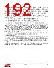
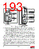
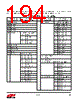
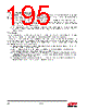
192 / 241 page  Rev 1.3 192 The NVIC also contains a software-configurable interrupt prioritization mechanism. The Reset, NMI, and Hard Fault exceptions, in that order, are always the highest priority, and are not software-configurable. All other exceptions can be assigned a 5-bit priority number, with low values representing higher priority. If any exceptions have the same software-configurable priority, then the NVIC uses the hardware-defined priority. The hardware- defined priority number is the same as the position of the exception in the exception table. For example, if IRQA and IRQB both fire at the same time and have the same software-defined priority, the NVIC handles IRQA, with priority number 28, first because it has a higher hardware priority than IRQB with priority number 29. The top-level interrupts are controlled through five ARM® CortexTM-M3 NVIC registers: INT_CFGSET, INT_CFGCLR, INT_PENDSET, INT_PENDCLR, and INT_ACTIVE. Writing 0 into any bit in any of these five register is ineffective. INT_CFGSET—Writing 1 to a bit in INT_CFGSET enables that top-level interrupt. INT_CFGCLR—Writing 1 to a bit in INT_CFGCLR disables that top-level interrupt. INT_PENDSET—Writing 1 to a bit in INT_PENDSET triggers that top-level interrupt. INT_PENDCLR—Writing 1 to a bit in INT_PENDCLR clears that top-level interrupt. INT_ACTIVE cannot be written to and is used for indicating which interrupts are currently active. INT_PENDSET and INT_PENDCLR set and clear a simple latch; INT_CFGSET and INT_CFGCLR set and clear a mask on the output of the latch. Interrupts may be pended and cleared at any time, but any pended interrupt will not be taken unless the corresponding mask (INT_CFGSET) is set, which allows that interrupt to propagate. If an INT_CFGSET bit is set and the corresponding INT_PENDSET bit is set, then the interrupt will propagate and be taken. If INT_CFGSET is set after INT_PENDSET is set, then the interrupt will also propagate and be taken. Interrupt flags (signals) from the top-level interrupts are level-sensitive. The second-level interrupt registers, which provide control of the second-level Event Manager peripheral interrupts, are described in “11.2. Event Manager” . For further information on the NVIC and ARM® CortexTM-M3 exceptions, refer to the ARM® CortexTM-M3 Technical Reference Manual and the ARM ARMv7-M Architecture Reference Manual. 11.2. Event Manager While the standard ARM® CortexTM-M3 Nested Vectored Interrupt Controller provides top-level interrupts into the CPU, the proprietary Event Manager provides second-level interrupts. The Event Manager takes a large variety of hardware interrupt sources from the peripherals and merges them into a smaller group of interrupts in the NVIC. Effectively, all second-level interrupts from a peripheral are “ORd” together into a single interrupt in the NVIC. In addition, the Event Manager provides missed indicators for the top-level peripheral interrupts with the register INT_MISS. The description of each peripheral's interrupt configuration and flag registers can be found in the chapters of this datasheet describing each peripheral. Figure 11.1 shows the Peripheral Interrupts Block Diagram. |
|
链接网址 |
| ALLDATASHEET是否为您带来帮助? [ DONATE ] |
关于 Alldatasheet | 广告服务 | 联系我们 | 隐私政策 | 数据表链接 | 链接交换 | 制造商名单 All Rights Reserved©Alldatasheet.com |
| Russian : Alldatasheetru.com | Korean : Alldatasheet.co.kr | Spanish : Alldatasheet.es | French : Alldatasheet.fr | Italian : Alldatasheetit.com Portuguese : Alldatasheetpt.com | Polish : Alldatasheet.pl | Vietnamese : Alldatasheet.vn Indian : Alldatasheet.in | Mexican : Alldatasheet.com.mx | British : Alldatasheet.co.uk | New Zealand : Alldatasheet.co.nz |
|
Family Site : ic2ic.com |
icmetro.com |
 Chinese ▼
 English
 Chinese
 German
 Japanese
 Russian
 Korean
 Spanish
 French
 Italian
 Portuguese
 Polish
 Vietnamese
 Indian
 Mexican
 British
 New Zealand