|
数据搜索系统,热门电子元器件搜索 |
|
|
数据搜索系统,热门电子元器件搜索 |
|
EM357-RTR 数据表(PDF) 209 Page - Silicon Laboratories |
|
|
|||||||||||||||||||||||||||||
EM357-RTR 数据表(HTML) 209 Page - Silicon Laboratories |
|
|
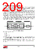
209 / 241 page  Rev 1.3 209 17. Serial Wire and JTAG (SWJ) Interface The EM35x includes a standard Serial Wire and JTAG (SWJ) Interface. The SWJ is the primary debug and programming interface of the EM35x. The SWJ gives debug tools access to the internal buses of the EM35x and allows for non-intrusive memory and register access as well as CPU halt-step style debugging. Therefore, any design implementing the EM35x should make the SWJ signals readily available. Serial Wire is an ARM® standard, bidirectional, two-wire protocol designed to replace JTAG and provides all the normal JTAG debug and test functionality. JTAG is a standard five-wire protocol providing debug and test functionality. In addition, the two Serial Wire signals (SWDIO and SWCLK) are overlaid on two of the JTAG signals (JTMS and JTCK). This keeps the design compact and allows debug tools to switch between Serial Wire and JTAG as needed, without changing pin connections. While Serial Wire and JTAG offer the same debug and test functionality, Silicon Labs recommends Serial Wire. Serial Wire uses only two pins instead of five, and offers a simple communication protocol, high performance data rates, low power, built-in error detection, and protection from glitches. The ARM CoreSight™ Debug Access Port (DAP) comprises the Serial Wire and JTAG Interface (SWJ). As illustrated in Figure 17.1, the DAP includes two primary components: a debug port (the SWJ-DP) and an access port (the AHB-AP). The SWJ-DP provides external debug access while the AHB-AP provides internal bus access. An external debug tool connected to the EM35x's debug pins communicates with the SWJ-DP. The SWJ-DP then communicates with the AHB-AP. Finally, the AHB-AP communicates on the internal bus. Figure 17.1. SWJ Block Diagram Serial Wire and JTAG share five pins: JRST JTDO JTDI SWDIO/JTMS SWCLK/JTCK Note: The SWJ pins are forced functions, and their corresponding GPIO_PxCFGH/L configurations are overridden when the EM35x resets. An application must disable all debug SWJ debug functionality to reclaim any of the four SWJ GPIOs: PC0, PC2, PC3, and PC4. Since these pins can be repurposed, refer to "19. Pin Definitions" on page 211 and "7.3. Forced Functions" on page 52 for complete pin descriptions and configurations. For further information on the SWJ, contact customer support for application notes and ARM® CoreSight™ documentation. SWJ-DP SWJ-DP Select SWJ-DAP SW Interface JTAG Interface Control and AP Interface Pins AHB-AP AHB |
|
链接网址 |
| ALLDATASHEET是否为您带来帮助? [ DONATE ] |
关于 Alldatasheet | 广告服务 | 联系我们 | 隐私政策 | 数据表链接 | 链接交换 | 制造商名单 All Rights Reserved©Alldatasheet.com |
| Russian : Alldatasheetru.com | Korean : Alldatasheet.co.kr | Spanish : Alldatasheet.es | French : Alldatasheet.fr | Italian : Alldatasheetit.com Portuguese : Alldatasheetpt.com | Polish : Alldatasheet.pl | Vietnamese : Alldatasheet.vn Indian : Alldatasheet.in | Mexican : Alldatasheet.com.mx | British : Alldatasheet.co.uk | New Zealand : Alldatasheet.co.nz |
|
Family Site : ic2ic.com |
icmetro.com |
 Chinese ▼
 English
 Chinese
 German
 Japanese
 Russian
 Korean
 Spanish
 French
 Italian
 Portuguese
 Polish
 Vietnamese
 Indian
 Mexican
 British
 New Zealand