|
数据搜索系统,热门电子元器件搜索 |
|
|
数据搜索系统,热门电子元器件搜索 |
|
EM357-RTR 数据表(PDF) 128 Page - Silicon Laboratories |
|
|
|||||||||||||||||||||||||||||
EM357-RTR 数据表(HTML) 128 Page - Silicon Laboratories |
|
|
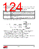
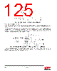
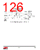
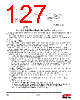
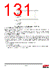
128 / 241 page  Rev 1.3 128 To detect missed captures reliably, read captured data in TIMxCCRy before checking the missed capture/compare flag. This sequence avoids missing a capture that could happen after reading the flag and before reading the data. Note: Software can generate IC interrupt requests by setting the corresponding TIM_CCyG bit in the TIMx_EGR register. 9.3.6. PWM Input Mode This mode is a particular case of input capture mode. The procedure is the same except: Two ICy signals are mapped on the same TIy input. These two ICy signals are active on edges with opposite polarity. One of the two TIyFP signals is selected as trigger input and the slave mode controller is configured in reset mode. For example, to measure the period in the TIMx_CCR1 register and the duty cycle in the TIMx_CCR2 register of the PWM applied on TI1, use the following procedure depending on CK_INT frequency and prescaler value: Select the active input for TIMx_CCR1: write the TIM_CC1S bits to 01 in the TIMx_CCMR1 register (TI1 selected). Select the active polarity for TI1FP1, used both for capture in the TIMx_CCR1 and counter clear, by writing the TIM_CC1P bit to 0 (active on rising edge). Select the active input for TIMx_CCR2by writing the TIM_CC2S bits to 10 in the TIMx_CCMR1 register (TI1 selected). Select the active polarity for TI1FP2 (used for capture in the TIMx_CCR2) by writing the TIM_CC2P bit to 1 (active on falling edge). Select the valid trigger input by writing the TIM_TS bits to 101 in the TIMx_SMCR register (TI1FP1 selected). Configure the slave mode controller in reset mode by writing the TIM_SMS bits to 100 in the TIMx_SMCR register. Enable the captures by writing the TIM_CC1E and TIM_CC2E bits to 1 in the TIMx_CCER register. Figure 9.20 illustrates this example. Figure 9.20. PWM Input Mode Timing |
|
链接网址 |
| ALLDATASHEET是否为您带来帮助? [ DONATE ] |
关于 Alldatasheet | 广告服务 | 联系我们 | 隐私政策 | 数据表链接 | 链接交换 | 制造商名单 All Rights Reserved©Alldatasheet.com |
| Russian : Alldatasheetru.com | Korean : Alldatasheet.co.kr | Spanish : Alldatasheet.es | French : Alldatasheet.fr | Italian : Alldatasheetit.com Portuguese : Alldatasheetpt.com | Polish : Alldatasheet.pl | Vietnamese : Alldatasheet.vn Indian : Alldatasheet.in | Mexican : Alldatasheet.com.mx | British : Alldatasheet.co.uk | New Zealand : Alldatasheet.co.nz |
|
Family Site : ic2ic.com |
icmetro.com |
 Chinese ▼
 English
 Chinese
 German
 Japanese
 Russian
 Korean
 Spanish
 French
 Italian
 Portuguese
 Polish
 Vietnamese
 Indian
 Mexican
 British
 New Zealand