|
数据搜索系统,热门电子元器件搜索 |
|
|
数据搜索系统,热门电子元器件搜索 |
|
CY8CKIT-059 数据表(PDF) 21 Page - Infineon Technologies AG |
|
|
|||||||||||||||||||||||||||||
CY8CKIT-059 数据表(HTML) 21 Page - Infineon Technologies AG |
|
|
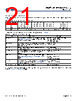
21 / 140 page  Document Number: 001-84932 Rev. *N Page 20 of 139 PSoC® 5LP: CY8C58LP Family Datasheet 5.5 Nonvolatile Latches (NVLs) PSoC has a 4-byte array of nonvolatile latches (NVLs) that are used to configure the device at reset. The NVL register map is shown in Table 5-3. The details for individual fields and their factory default settings are shown in Table 5-3:. Although PSoC Creator provides support for modifying the device configuration NVLs, the number of NVL erase/write cycles is limited – see “Nonvolatile Latches (NVL)” on page 117. Table 5-2. Device Configuration NVL Register Map Register Address 7 6 5 4 3 2 1 0 0x00 PRT3RDM[1:0] PRT2RDM[1:0] PRT1RDM[1:0] PRT0RDM[1:0] 0x01 PRT12RDM[1:0] PRT6RDM[1:0] PRT5RDM[1:0] PRT4RDM[1:0] 0x02 XRESMEN DBGEN PRT15RDM[1:0] 0x03 DIG_PHS_DLY[3:0] ECCEN DPS[1:0] CFGSPEED Table 5-3. Fields and Factory Default Settings Field Description Settings PRTxRDM[1:0] Controls reset drive mode of the corresponding IO port. See “Reset Configuration” on page 39. All pins of the port are set to the same mode. 00b (default) - high impedance analog 01b - high impedance digital 10b - resistive pull up 11b - resistive pull down XRESMEN Controls whether pin P1[2] is used as a GPIO or as an external reset. P1[2] is generally used as a GPIO, and not as an external reset. 0 (default) - GPIO 1 - external reset DBGEN Debug Enable allows access to the debug system, for third-party programmers. 0 - access disabled 1 (default) - access enabled CFGSPEED Controls the speed of the IMO-based clock during the device boot process, for faster boot or low-power operation 0 (default) - 12 MHz IMO 1 - 48 MHz IMO DPS[1:0] Controls the usage of various P1 pins as a debug port. See “Programming, Debug Interfaces, Resources” on page 61. 00b - 5-wire JTAG 01b (default) - 4-wire JTAG 10b - SWD 11b - debug ports disabled ECCEN Controls whether ECC flash is used for ECC or for general configuration and data storage. See “Flash Program Memory” on page 19. 0 - ECC disabled 1 (default) - ECC enabled DIG_PHS_DLY[3:0] Selects the digital clock phase delay. See the TRM for details. |
|
链接网址 |
| ALLDATASHEET是否为您带来帮助? [ DONATE ] |
关于 Alldatasheet | 广告服务 | 联系我们 | 隐私政策 | 数据表链接 | 链接交换 | 制造商名单 All Rights Reserved©Alldatasheet.com |
| Russian : Alldatasheetru.com | Korean : Alldatasheet.co.kr | Spanish : Alldatasheet.es | French : Alldatasheet.fr | Italian : Alldatasheetit.com Portuguese : Alldatasheetpt.com | Polish : Alldatasheet.pl | Vietnamese : Alldatasheet.vn Indian : Alldatasheet.in | Mexican : Alldatasheet.com.mx | British : Alldatasheet.co.uk | New Zealand : Alldatasheet.co.nz |
|
Family Site : ic2ic.com |
icmetro.com |
 Chinese ▼
 English
 Chinese
 German
 Japanese
 Russian
 Korean
 Spanish
 French
 Italian
 Portuguese
 Polish
 Vietnamese
 Indian
 Mexican
 British
 New Zealand