|
数据搜索系统,热门电子元器件搜索 |
|
|
数据搜索系统,热门电子元器件搜索 |
|
EM357-RTR 数据表(PDF) 184 Page - Silicon Laboratories |
|
|
|||||||||||||||||||||||||||||
EM357-RTR 数据表(HTML) 184 Page - Silicon Laboratories |
|
|
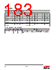
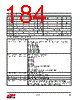
184 / 241 page  Rev 1.3 184 Address: 0x4000D004 Reset: 0x00001800 Register 10.2. ADC_CFG: ADC Configuration Register Bit 31 30 29 28 27 26 25 24 Name 0 0 0 0 0 0 0 0 Bit 23 22 21 20 19 18 17 16 Name 0 0 0 0 0 0 0 0 Bit 15 14 13 12 11 10 9 8 Name ADC_PERIOD ADC_CFGRSVD2 ADC_MUXP Bit 7 6 5 4 3 2 1 0 Name ADC_MUXP ADC_MUXN ADC_1MHZCLK ADC_CFGRSVD ADC_ENABLE Bitname Bitfield Access Description ADC_PERIOD [15:13] RW ADC sample time in clocks and the equivalent significant bits in the conversion. 0: 32 clocks (7 bits). 1: 64 clocks (8 bits). 2: 128 clocks (9 bits). 3: 256 clocks (10 bits). 4: 512 clocks (11 bits). 5: 1024 clocks (12 bits). 6: 2048 clocks (13 bits). 7: 4096 clocks (14 bits). ADC_CFGRSVD2 [12:11] RW Reserved: these bits must be set to 0. ADC_MUXP [10:7] RW Input selection for the P channel. 0x0: PB5 pin. 0x1: PB6 pin. 0x2: PB7 pin. 0x3: PC1 pin. 0x4: PA4 pin. 0x5: PA5 pin. 0x8: GND (0V) (not for high voltage range). 0x9: VREF/2 (0.6 V). 0xA: VREF (1.2 V). 0xB: VDD_PADSA/2 (0.9 V) (not for high voltage range). 0x6, 0x7, 0xC-0xF: Reserved. ADC_MUXN [6:3] RW Input selection for the N channel. Refer to ADC_MUXP above for choices. ADC_1MHZCLK [2] RW Select ADC clock: 0 = 6 MHz, 1 = 1 MHz. ADC_CFGRSVD [1] RW Reserved: this bit must always be set to 0. ADC_ENABLE [0] RW Enable the ADC: write 1 to enable continuous conversions, write 0 to stop. When the ADC is started the first conversion takes twice the usual number of clocks plus 21 microseconds. If anything in this register is modified while the ADC is run- ning, the next conversion takes twice the usual number of clocks. |
|
链接网址 |
| ALLDATASHEET是否为您带来帮助? [ DONATE ] |
关于 Alldatasheet | 广告服务 | 联系我们 | 隐私政策 | 数据表链接 | 链接交换 | 制造商名单 All Rights Reserved©Alldatasheet.com |
| Russian : Alldatasheetru.com | Korean : Alldatasheet.co.kr | Spanish : Alldatasheet.es | French : Alldatasheet.fr | Italian : Alldatasheetit.com Portuguese : Alldatasheetpt.com | Polish : Alldatasheet.pl | Vietnamese : Alldatasheet.vn Indian : Alldatasheet.in | Mexican : Alldatasheet.com.mx | British : Alldatasheet.co.uk | New Zealand : Alldatasheet.co.nz |
|
Family Site : ic2ic.com |
icmetro.com |
 Chinese ▼
 English
 Chinese
 German
 Japanese
 Russian
 Korean
 Spanish
 French
 Italian
 Portuguese
 Polish
 Vietnamese
 Indian
 Mexican
 British
 New Zealand