|
数据搜索系统,热门电子元器件搜索 |
|
|
数据搜索系统,热门电子元器件搜索 |
|
EM357-RTR 数据表(PDF) 177 Page - Silicon Laboratories |
|
|
|||||||||||||||||||||||||||||
EM357-RTR 数据表(HTML) 177 Page - Silicon Laboratories |
|
|
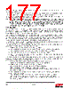
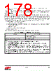
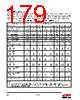
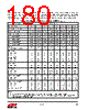
177 / 241 page  177 Rev 1.3 Bits in INT_ADCFLAG register may be cleared by writing a 1 to their position. Writing 0 to any bit in the INT_ADCFLAG register is ineffectual. The INT_ADCCFG register controls whether or not INT_ADCFLAG register bits actually propagate the ADC interrupt to the NVIC. Only the events whose bits are 1 in the INT_ADCCFG register can do so. For non-interrupt (polled) ADC operation set the INT_ADCCFG register to zero, and read the bit flags in the INT_ADCFLAG register to determine the ADC status. Note: When making changes to the ADC configuration it is best to disable the DMA beforehand. If this isn’t done it can be diffi- cult to determine at which point the sampled data in the DMA buffer switched from the old configuration to the new con- figuration. However, since the ADC will be left running, if it completes a conversion after the DMA is disabled, the INT_ADCOVF flag will be set. To prevent these unwanted DMA buffer overflow indications, clear the INT_ADCOVF flag immediately after enabling the DMA, preferably with interrupts off. Disabling the ADC in addition to the DMA is often undesirable because of the additional analog startup time when it is re-enabled. 10.3. Operation Setting the ADC_EN bit in the ADC_CFG register enables the ADC. Once the ADC is enabled, it performs conversions continuously until it is disabled. If the ADC had previously been disabled, a 21 µs analog startup delay is automatically imposed before the ADC starts conversions. The delay timing is performed in hardware and is simply added to the time until the first conversion result is output. When the ADC is first enabled, and/or if any change is made to ADC_CFG after it is enabled, the time until a result is output is double the normal sample time. This is because the ADC’s internal design requires it to discard the first conversion after startup or a configuration change. This is done automatically and is hidden from software. Switching the system clock between OSCHF and OSC24M also causes the ADC to go through this startup cycle. If the ADC was newly enabled, the analog delay time is added to the doubled sample time. If the DMA is running when the ADC_CFG register is modified, the DMA does not stop, so the DMA buffer may contain conversion results from both the old and new configurations. The following procedure illustrates a simple polled method of using the ADC without DMA. This assumes that any GPIOs and the voltage reference have already been configured. 1. Disable all ADC interrupts: Write 0 to the INT_ADCCFG register. 2. Write the desired offset and gain correction values to the ADC_OFFSET and ADC_GAIN registers. 3. Write the desired conversion configuration, with the ADC_EN bit set, to ADC_CFG register. 4. Clear the ADC data flag: Write the INT_ADCDATA bit to INT_ADCFLAG register. 5. Wait until the INT_ADCDATA bit is set in INT_ADCFLAG register, then read the result, as a 16-bit signed variable, from the ADC_DATA register. The following procedure illustrates a simple polled method of using the ADC with DMA. After completing the procedure, the latest conversion results are available in the location written to by the DMA. This assumes that any GPIOs and the voltage reference have already been configured. 1. Allocate a 16-bit signed variable, for example analogData, to receive the ADC output. (Make sure that analogData is half-word aligned – that is, at an even address.) 2. Disable all ADC interrupts: Write 0 to the INT_ADCCFG register. 3. Set up the DMA to output conversion results to the variable, analogData. Reset the DMA: Set the ADC_DMARST bit in ADC_DMACFG register. Define a one sample buffer: Write analogData’s address to the ADC_DMABEG register and set the ADC_DMASIZE register to 1. 4. Write the desired offset and gain correction values to the ADC_OFFSET and ADC_GAIN registers. 5. Start the ADC and the DMA. Write the desired conversion configuration, with the ADC_EN bit set, to the ADC_CFG register. Clear the ADC buffer full flag: Write the INT_ADCULDFULL bit to the INT_ADCFLAG register. Start the DMA in auto wrap mode: Set the ADC_DMAAUTOWRAP and ADC_DMALOAD bits in the ADC_DMACFG register. |
|
链接网址 |
| ALLDATASHEET是否为您带来帮助? [ DONATE ] |
关于 Alldatasheet | 广告服务 | 联系我们 | 隐私政策 | 数据表链接 | 链接交换 | 制造商名单 All Rights Reserved©Alldatasheet.com |
| Russian : Alldatasheetru.com | Korean : Alldatasheet.co.kr | Spanish : Alldatasheet.es | French : Alldatasheet.fr | Italian : Alldatasheetit.com Portuguese : Alldatasheetpt.com | Polish : Alldatasheet.pl | Vietnamese : Alldatasheet.vn Indian : Alldatasheet.in | Mexican : Alldatasheet.com.mx | British : Alldatasheet.co.uk | New Zealand : Alldatasheet.co.nz |
|
Family Site : ic2ic.com |
icmetro.com |
 Chinese ▼
 English
 Chinese
 German
 Japanese
 Russian
 Korean
 Spanish
 French
 Italian
 Portuguese
 Polish
 Vietnamese
 Indian
 Mexican
 British
 New Zealand