|
数据搜索系统,热门电子元器件搜索 |
|
|
数据搜索系统,热门电子元器件搜索 |
|
EM357-RTR 数据表(PDF) 176 Page - Silicon Laboratories |
|
|
|||||||||||||||||||||||||||||
EM357-RTR 数据表(HTML) 176 Page - Silicon Laboratories |
|
|
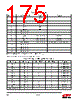
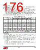
176 / 241 page  Rev 1.3 176 10.1.5.2. Input Range The single-ended input range is fixed as 0 V to VREF and the differential input range is fixed as -VREF to +VREF. 10.1.5.3. Sample Time ADC sample time is programmed by selecting the sampling clock and the clocks per sample. The sampling clock may be either 1 MHz or 6 MHz. If the ADC_1MHZCLK bit in the ADC_CFG register is clear, the 6 MHz clock is used; if it is set, the 1 MHz clock is selected. The 6 MHz sample clock offers faster conversion times but the ADC resolution is lower than that achieved with the 1 MHz clock. The number of clocks per sample is determined by the ADC_PERIOD bits in the ADC_CFG register. ADC_PERIOD values select from 32 to 4096 sampling clocks in powers of two. Longer sample times produce more significant bits. Regardless of the sample time, converted samples are always 16-bits in size with the significant bits left-aligned within the value. Table 10.4 shows the options for ADC sample times and the significant bits in the conversion results. 10.2. Interrupts The ADC has its own top-level interrupt in the NVIC. The ADC interrupt is enabled by writing the INT_ADC bit to the INT_CFGSET register, and cleared by writing the INT_ADC bit to the INT_CFGCLR register. "11. Interrupt System" on page 190, describes the interrupt system in detail. Five kinds of ADC events can generate an ADC interrupt, and each has a bit flag in the INT_ADCFLAG register to identify the reason(s) for the interrupt: INT_ADCOVF – an ADC conversion result was ready but the DMA was disabled (DMA buffer overflow). INT_ADCSAT– the gain correction multiplication exceeded the limits for a signed 16-bit number (gain saturation). INT_ADCULDFULL – the DMA wrote to the last location in the buffer (DMA buffer full). INT_ADCULDHALF – the DMA wrote to the last location of the first half of the DMA buffer (DMA buffer half full). INT_ADCDATA – there is data ready in the ADC_DATA register. Table 10.4. ADC Sample Times* ADC_PERIOD Sample Clocks Sample Time (µs) Sample Frequency (kHz) Significant Bits 1 MHz Clock 6 MHz Clock 1 MHz Clock 6 MHz Clock 0 32 32 5.33 31.3 188 7 1 64 64 10.7 15.6 93.8 8 2 128 128 21.3 7.81 46.9 9 3 256 256 42.7 3.91 23.4 10 4 512 512 85.3 1.95 11.7 11 5 1024 1024 170 0.977 5.86 12 6 2048 2048 341 0.488 2.93 13 7 4096 4096 682 0.244 1.47 14 *Note: ADC sample timing is the same whether the EM35x is using the 24 MHz crystal oscillator or the 12 MHz high-speed RC oscillator. This facilitates using the ADC soon after the CPU wakes from deep sleep, before switching to the crystal oscillator. |
|
链接网址 |
| ALLDATASHEET是否为您带来帮助? [ DONATE ] |
关于 Alldatasheet | 广告服务 | 联系我们 | 隐私政策 | 数据表链接 | 链接交换 | 制造商名单 All Rights Reserved©Alldatasheet.com |
| Russian : Alldatasheetru.com | Korean : Alldatasheet.co.kr | Spanish : Alldatasheet.es | French : Alldatasheet.fr | Italian : Alldatasheetit.com Portuguese : Alldatasheetpt.com | Polish : Alldatasheet.pl | Vietnamese : Alldatasheet.vn Indian : Alldatasheet.in | Mexican : Alldatasheet.com.mx | British : Alldatasheet.co.uk | New Zealand : Alldatasheet.co.nz |
|
Family Site : ic2ic.com |
icmetro.com |
 Chinese ▼
 English
 Chinese
 German
 Japanese
 Russian
 Korean
 Spanish
 French
 Italian
 Portuguese
 Polish
 Vietnamese
 Indian
 Mexican
 British
 New Zealand