|
数据搜索系统,热门电子元器件搜索 |
|
|
数据搜索系统,热门电子元器件搜索 |
|
ADP1050ACPZ-R7 数据表(PDF) 21 Page - Analog Devices |
|
|
|||||||||||||||||||||||||||||
ADP1050ACPZ-R7 数据表(HTML) 21 Page - Analog Devices |
|
|
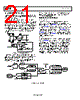
21 / 93 page  ADP1050 Data Sheet CS1 CURRENT SENSE (CS1 PIN) The CS1 current sense input (Pin 5) senses, protects, and controls the primary side input. CS1 can be calibrated to reduce errors due to the external components. Current Sense 1 (CS1) is typically used for the monitoring and protection of the primary side current, which is commonly sensed using a current transformer (CT). The input signal at the CS1 pin is fed into an ADC for current monitoring. The range of the ADC is 0 V to 1.60 V. The input signal is also fed into an analog comparator for cycle-by-cycle current limiting and IIN overcurrent fast protection, with a reference of 0.25 V or 1.2 V set by Register 0xFE1B[6]. The typical configuration for the CS1 current sense is shown in Figure 23. REFERENCE REG 0xFE1B[6] 12 BITS CYCLE-BY-CYCLE CURRENT LIMITING AND IIN FAST OCP CS1 ADC VIN Figure 23. Current Sense 1 (CS1) Operation The CS1 ADC is used to measure the average value of the primary side current. The ADC samples at a frequency of 1.56 MHz and reports a CS1 reading (12 bits) in the READ_IIN command (Register 0x89), with an asynchronously averaged rate of 10 ms, 52 ms, 105 ms, or 210 ms set by Register 0xFE65[1:0]. Various IIN overcurrent fast fault limits and response actions can be set for CS1. These are described in the Current Sense and Limit Setting Registers section. SOFT START AND SHUTDOWN On/Off Control The OPERATION command (Register 0x01) and the ON_OFF_ CONFIG command (Register 0x02) control the power-on and power-off behavior of the ADP1050. The OPERATION command turns the ADP1050 on and off in conjunction with input from the CTRL pin (Pin 13). The combination of the CTRL pin input and the serial bus commands required to turn the ADP1050 on and off is configured by the ON_OFF_CONFIG command. When the ADP1050 is commanded to turn on, the power supply on (PSON) signal is enabled, and the ADP1050 follows the soft start procedure to begin the power conversion. Soft Start After VDD power-up and initialization, the PSON signal is enabled when the ADP1050 is commanded to turn on. The controller waits for a user specified turn-on delay (TON_DELAY, Register 0x60) before initiating output voltage soft start ramp. The soft start is then performed by actively regulating the output voltage and digitally ramping up the target voltage to the commanded voltage setpoint. The rise time of the voltage ramp is programmed, using the TON_ RISE command (Register 0x61) to minimize the inrush currents associated with the start-up voltage ramp. A nonzero prebiased voltage results in a longer turn-on delay and shorter rise time. CTRL PIN REG 0x02[1] REG 0x01[7:6] REG 0x02[0] ON OFF IMMEDIATE OFF DELAY OFF OPERATION (SOFTWARE) ON REG 0x01[5:4] REG 0x02[4:2] ALWAYS ON ON/OFF OPERATION VOUT COMMAND VOUT MARGIN LOW VOUT MARGIN HIGH IMMEDIATE OFF DELAY OFF Figure 24. On/Off Control Diagram Rev. A | Page 20 of 92 |
|
链接网址 |
| ALLDATASHEET是否为您带来帮助? [ DONATE ] |
关于 Alldatasheet | 广告服务 | 联系我们 | 隐私政策 | 数据表链接 | 链接交换 | 制造商名单 All Rights Reserved©Alldatasheet.com |
| Russian : Alldatasheetru.com | Korean : Alldatasheet.co.kr | Spanish : Alldatasheet.es | French : Alldatasheet.fr | Italian : Alldatasheetit.com Portuguese : Alldatasheetpt.com | Polish : Alldatasheet.pl | Vietnamese : Alldatasheet.vn Indian : Alldatasheet.in | Mexican : Alldatasheet.com.mx | British : Alldatasheet.co.uk | New Zealand : Alldatasheet.co.nz |
|
Family Site : ic2ic.com |
icmetro.com |
 Chinese ▼
 English
 Chinese
 German
 Japanese
 Russian
 Korean
 Spanish
 French
 Italian
 Portuguese
 Polish
 Vietnamese
 Indian
 Mexican
 British
 New Zealand