|
数据搜索系统,热门电子元器件搜索 |
|
|
数据搜索系统,热门电子元器件搜索 |
|
ADP1050ACPZ-R7 数据表(PDF) 22 Page - Analog Devices |
|
|
|||||||||||||||||||||||||||||
ADP1050ACPZ-R7 数据表(HTML) 22 Page - Analog Devices |
|
|
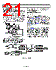
22 / 93 page  Data Sheet ADP1050 PSON SIGNAL TON_DELAY REG 0x60 TON_RISE REG 0x61 HF ADC SETTLING DEBOUNCE REG 0xFE3D[5:4] PGOOD DEBOUNCE REG 0xFE0E[3:2] VOUT SOFT_START_FILTER FLAG REG 0xFEA2[0] POWER_OFF FLAG REG 0x78[6] AND REG 0x79[6] t0 t1 t2 t3 t4 PG/ALT PIN Figure 25. Soft Start Timing Diagram When the user turns on the power supply, the following soft start procedure is initiated (see Figure 25): 1. At t0, the PSON signal is enabled by using the OPERATION command, the ON_OFF_CONFIG command, and/or the CTRL pin. The ADP1050 verifies that the initial flags indicate no abnormalities. 2. The ADP1050 waits for the programmed TON_DELAY time to ramp up the power stage voltage at t1. The soft start filter gain (set by Register 0xFE3D[1:0]) is used for closed-loop control. 3. The soft start begins to ramp up the internal reference. The soft start ramp time is programmed using the TON_RISE command. 4. At t2, the soft start ramp reaches the output voltage setpoint. The high frequency ADC starts to settle. 5. Additional high frequency ADC settling debounce time can be programmed using Register 0xFE3D[5:4]. If the debounce time is used, the high frequency ADC is activated at t3. The period between t2 and t3 is the high frequency ADC settling debounce time. At t3, the control loop is switched from the soft start filter to the normal filter. If no faults are present, the PGOOD signal waits for the programmed clearing debounce time (Register 0xFE0E[3:2]) before the PG/ALT pin is pulled high at t4. If a fault condition occurs during the soft start ramp (the time set by the TON_RISE command, t1 to t2), the ADP1050 responds as programmed, unless the flag is blanked during soft start. The user can program which flags are active during the soft start. All flags are active at the end of the soft start ramp (t2). See the Flag Blanking During Soft Start section for more information. The SR1 and SR2 outputs and the volt-second balance functions can also be disabled during the soft start ramp. For more information, see the Synchronous Rectification section and the Volt-Second Balance Control section, respectively. Digital Filters During Soft Start A dedicated soft start filter is used during soft start. The soft start filter is a pure low frequency filter with a programmable gain. The filter is disabled at the end of the soft start routine (t2), and then the general digital compensator is used. The soft start filter gain is programmed using Register 0xFE3D[1:0]. The soft start filter is used during the ramp time of the voltage reference, until the VS high frequency ADC is settled. The user can program (using Register 0xFE3D[4]) whether a high frequency ADC debounce time is added. The high frequency ADC debounce time is the interval from when the high frequency ADC is settled to when the frequency filter takes action. The debounce time can be programmed at 5 ms or 10 ms using Register 0xFE3D[5]. During the time when the soft start filter is in use, the SOFT_ START_FILTER flag is set. It is recommended that a high frequency ADC debounce time not be used if the fast load transient occurs during soft start. Software Reset The software reset command allows the user to perform a software reset of the ADP1050. When a 1 is written to Register 0xFE06[0], the power supply is immediately turned off and then restarted with a soft start following a restart delay. The restart delay time can be programmed as 0 ms, 500 ms, 1 sec, or 2 sec (Register 0xFE07[1:0]). If both TON_DELAY and the restart delay are programmed with 0 ms, a write to Register 0xFE06[0] does nothing. Shutdown When the ADP1050 is commanded to turn off, the PSON signal is cleared. Depending on the setting of the OPERATION command, the ADP1050 shuts down immediately or waits for a user specified turn-off delay (TOFF_DELAY) prior to the shutdown action. If the ADP1050 is turned off because a fault condition occurs, the shutdown actions are programmed by the specific fault flag responses. See the Power Monitoring, Flags, and Fault Responses section for more information. The PGOOD flag setting debounce time can be programmed in Register 0xFE0E[1:0]). This debounce time is from when the PGOOD setting condition is met to when the PGOOD flag is set and the PG/ALT pin is pulled low. Rev. A | Page 21 of 92 |
|
链接网址 |
| ALLDATASHEET是否为您带来帮助? [ DONATE ] |
关于 Alldatasheet | 广告服务 | 联系我们 | 隐私政策 | 数据表链接 | 链接交换 | 制造商名单 All Rights Reserved©Alldatasheet.com |
| Russian : Alldatasheetru.com | Korean : Alldatasheet.co.kr | Spanish : Alldatasheet.es | French : Alldatasheet.fr | Italian : Alldatasheetit.com Portuguese : Alldatasheetpt.com | Polish : Alldatasheet.pl | Vietnamese : Alldatasheet.vn Indian : Alldatasheet.in | Mexican : Alldatasheet.com.mx | British : Alldatasheet.co.uk | New Zealand : Alldatasheet.co.nz |
|
Family Site : ic2ic.com |
icmetro.com |
 Chinese ▼
 English
 Chinese
 German
 Japanese
 Russian
 Korean
 Spanish
 French
 Italian
 Portuguese
 Polish
 Vietnamese
 Indian
 Mexican
 British
 New Zealand